Creating Midi controllers with arduinos
A warning to my non-technical friends: The following post is long and technically detailed. You might want to just check out the pictures and move on, but i’m hoping I can save a few people some hours of work by detailing everything I went through.
My son was interested in using a midi controller that used the distance your hand was above it to control his DJ rig with Ableton Live on his mac. I had done previous arduino midi projects with a midi shield from Sparkfun, but his mac doesn’t really have a native Midi interface. I found out that the midi standard now specifies a way of transporting midi over USB, and in fact most of the modern keyboard controllers, etc have this built in. Unfortunately. until recently, the USB interface of arduinos was a simple usb to serial controller chip that requires a driver, etc. People have written software drivers that convert between these (described here), but I felt that this was too complicated. There’s a commercial arduino-like clone that supports midi very easily (the Teensy) that I’ll talk about in a later post, because in fact, it’s actually a lot easier to use than what I ended up doing.
Arduino UNO to the rescue!
Instead of the USB-serial chip of previous arduinos, the UNO actually has a second microprocessor which is one of the USB enabled ATMEGAs, the ATMEGA 8U2. There’s even a bootloader in it that allows you to use Atmel’s DFU/flip protocol to load code.
Unfortunately, when I started, it was very difficult to figure out how to get this going, so I ended up trying to program the chip directly.
Making LUFA applications for the ATMEGA 8U2
A very cool guy who is very into ATMEL micro’s has written a wonderful library for just about every class compliant USB device to run on the ATMEGA processors. Dean Camera’s LUFA (Lightweight USB Framework for AVRs) can be found at Dean’s website; http://www.fourwalledcubicle.com/LUFA.php
One thing that wasn’t obvious to me in building LUFA applications is that the individual projects drive the build process. In other words if you do a top level build, and then drop down to your new project directory, you’ll get errors. So if you have already built LUFA, do a make clean at the top level, then cd to your project directory and do the make from there.
There are several good examples to start from and I wanted to make sure I could restore the UNO’s firmware, so first I built arduino-usbserial. This can be retrieved from the arduino repository or in the hardware/firmware directory of the arduino distribution.
The version distributed with Arduino-0022 seems to be incompatible with the latest version of LUFA(101122) but compiles nicely with LUFA 100807. Note that the following assumes you’ve already installed winavr (or the your platform’s equivalent)
- Download Lufa from http://www.fourwalledcubicle.com/LUFA.php
Specifically I used:
http://lufa-lib.googlecode.com/files/LUFA-100807.zip
- Copy arduino-usbserial from arduino-xxxxx\hardware/arduino\firmwares\ to the project directory of LUFA. In my case this is c:\LUFA 100807\projects
- cd to the arduino-usbserial directory you just made in LUFA and type make. Note I edited the makefile to use usbtinyisp for programming.
Getting the code on the ATMEGA8U2
There are two choices for loading the code onto the 8U2:
- Using the pre-programmed DFU bootloader. The instructions are now a little clearer, but still hard to find. Here’s the link.
- Soldering in the ISP header and using an ISP programmer such as Adafruit’s usbtinyisp I dried this first, and somehow bricked the usb part of the UNO. I can still upload code to either processor using USB tinyisp, but no USB goodness. I bought a smd version of the UNO which had the programming header in place and I was off to the races.
Moco lufa!
I was starting to look into the midi example in LUFA, but after several exchanged on the adafruit forums, user morecat_labpointed to his project which is a very nicely done firmware for avr usb micros to do a serial to usb-midi conversion.
The MocoLUFA firmware (Thanks Yoshi!! (morecat_lab) works terrific, unmodified on my new SMD uno (which took forever to get here, by the way, grumble grumble)
First you need to download Moco for LUFA from Yoshi’s site: http://web.mac.com/kuwatay/morecat_lab./MocoLUFA.html
Since the existing Midi library uses the 328 serial port and the MOCA firmware relays those (repackaging them as USB messages), The midi code is trivial to implement. The only fiddly bit is that once you’ve reprogrammed the 8U2, you need to either restore it to load the 328 code, or use an isp programmer (which I recommend)
I still can’t get the hang of the DFU bootloading stuff (and the jumper pads seem to not be there for the SMD version), but fortunately the SMD UNO comes with the ATMEGA8U2 ISP programming header.
One detail that’s important: If you want to recompile the usb-serial firmware, you need an older version of LUFA, while the MOCO stuff compiles under the latest version. (Dean Camera apparently reorganized a lot of the headers which makes the application code incompatible without modification)
Here’s the version you need for MOCO:http://lufa-lib.googlecode.com/files/LUFA-101122.zip
To restore the original bootloader, you can either save out the contents of flash and restore it, or use one of the hex files in the arduino[xxx]/hardware/arduino/firmwares directory.
The MOCA interface loads automatically in Windows 7 (takes a while, but does configure) and instantly in MAC OSX
Theremin-like…
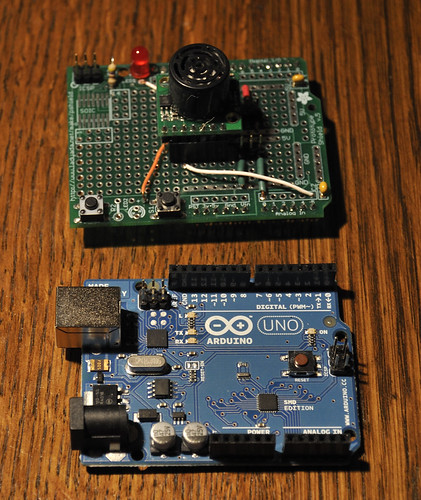
Well, a real theremin uses antennas and radio waves to modulate sound based on your hand position. I used distance sensors commonly used in hobby robotics. I made two version, one with the ultrasonic MAXBOTICS LV-EZ-1 which you can buy from Adafruit, Sparkfun, etc., and a Sharp IR sensor available from the same places. The Sharp IR version went into a box with a Teensy (which was kindof broken) so I’ll write about that later when I get the parts to finish it.
The Midi Bits.
The Maxbotics part is pretty easy to use. It has a proportional analog voltage output, RS232, and PWM. I hooked the analog output to one of the arduino analog inputs. The output is a bit noisy, and jumps around a little, so I resorted to a running average to smooth it out. This means I take several samples (configurable) average the last x number and report the mean of those samples.
Grant wanted midi CC (control change messages) to map to different music parameters (looping etc.) so I wired that in, however I didn’t have anything as fancy as his software, so for testing, I had it output note-on and note-off messages. I used a freeware program for windows called midi-ox


 Once again, this whole project wouldn’t have been possible without my adafruit usbtiny ISP programmer. I used an Evil Mad Scientist minimal target board to program the chip.
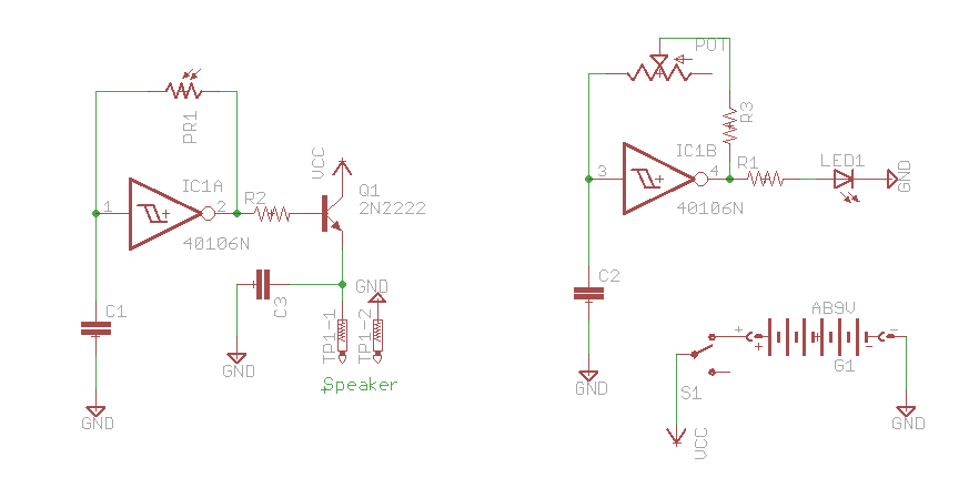
 I’ve had a lot of fun with my TV-B-Gone, which I bought direct from Mitch Altman (the inventor) at Maker-Faire RI a couple of years ago. I particularly like turning off the plague of flatscreens at work, and every one I can see through the glass doors in my building!
 The actual hack took less than a half hour. I found someone else had done the reverse engineering of the timing on the web (