Category Archives: Raspberry Pi

NovaBooth – Improving the Open Source Photobooth

NoVa Snap
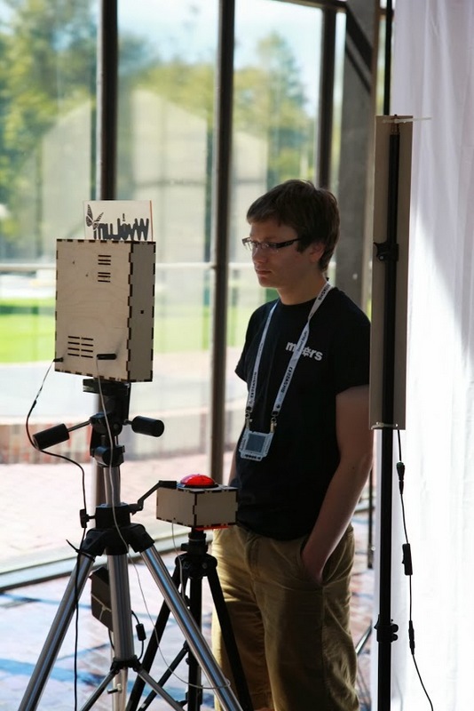
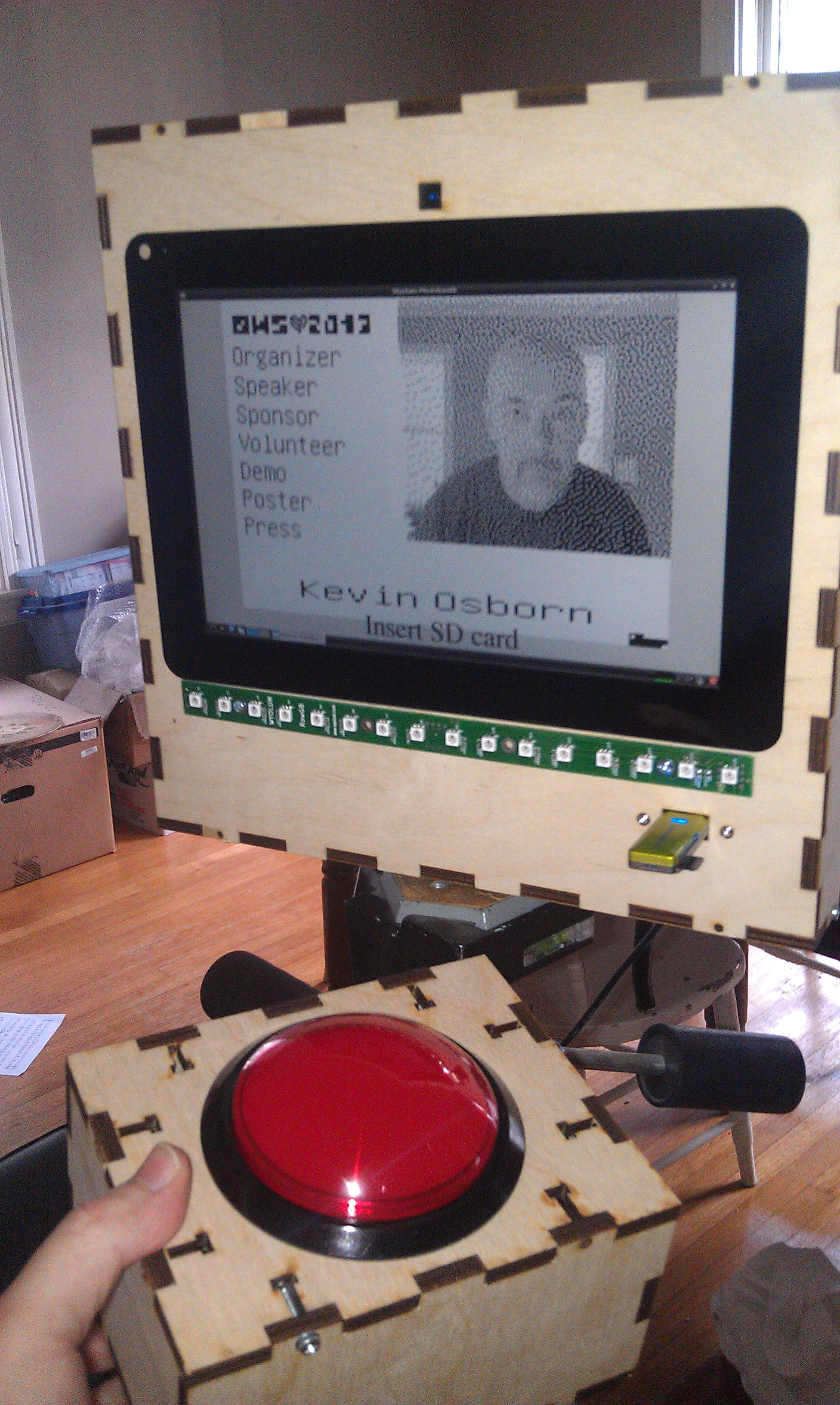
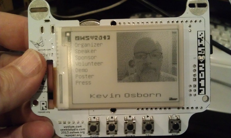
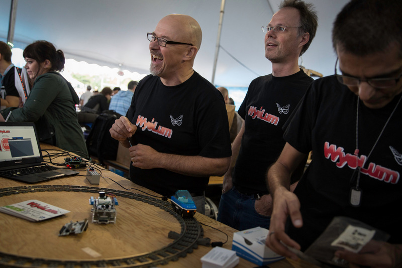
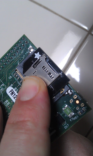
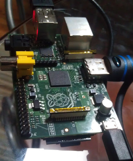
As you may have read here previously, we (the Wyolum Gang) created a photobooth for the Open Hardware Summit, for the purpose of customizing the e-paper badges we made for the conference attendees. This processed the pictures into a small black and white image for the e-paper badge, and saved it onto the badge’s micro-sd card.

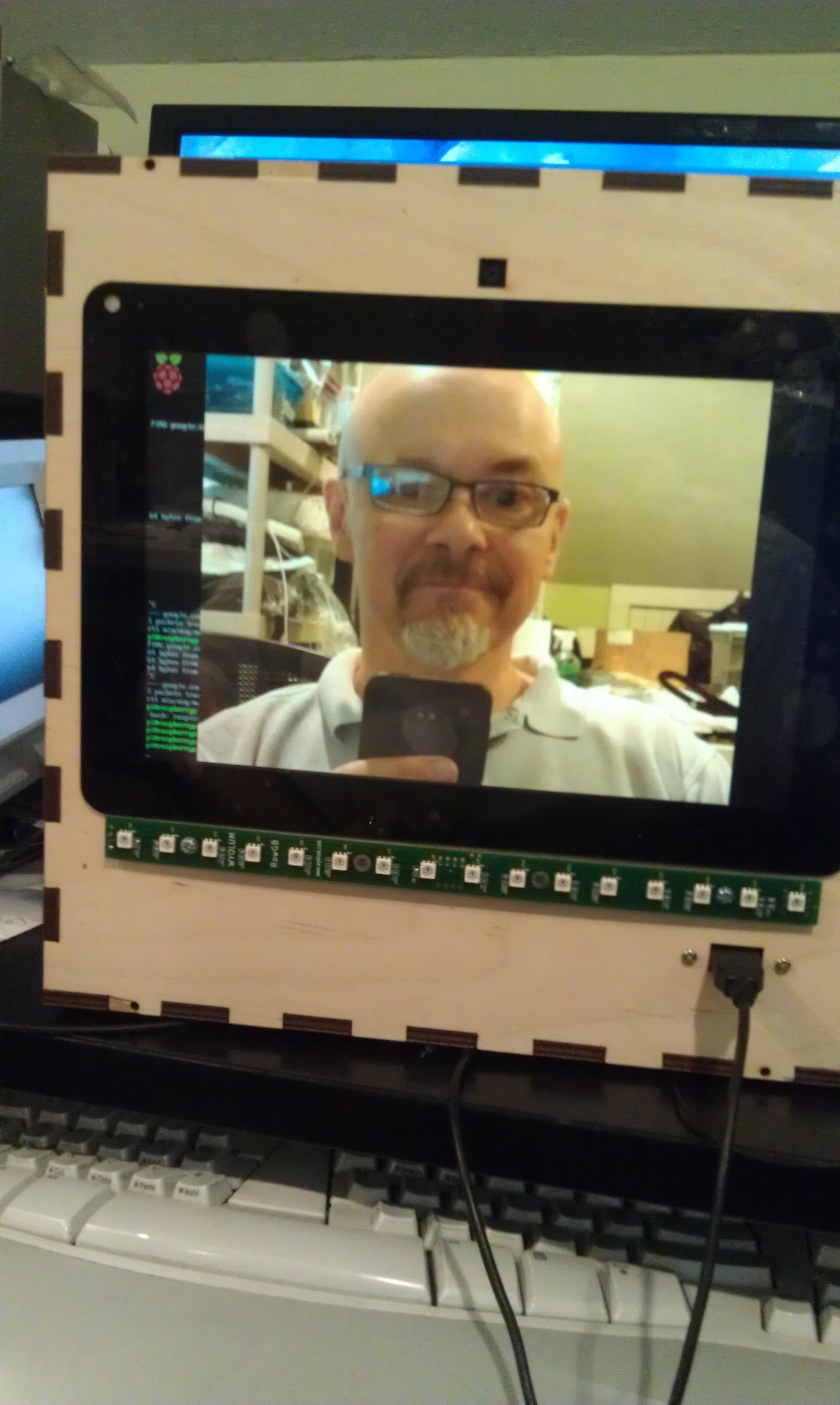
I was headed to help out at the Northern Virginia Maker Faire, and thought it would be fun to update the photobooth to take full color pictures, upload them to the Internet and offer to email them to friends and relatives.

The email message and logo files are easy to add and customize.

For basic construction, visit the original post, but download the new software here:

github: https://github.com/wyolum/NovaBooth

The fabricate directory has the laser cut files, arduino for the AlaMode Program, and scripts for the python photobooth code.

Edit custom.py to customize the email subject and message. config.py contains the authentication information for the google email and posting accounts. You’ll need to set up application specific passwords for this on your google account. You can use the same account, or separate.

Wireless keyboard, had to add a powered hub.

Problems

  • External powered hub was a pain.
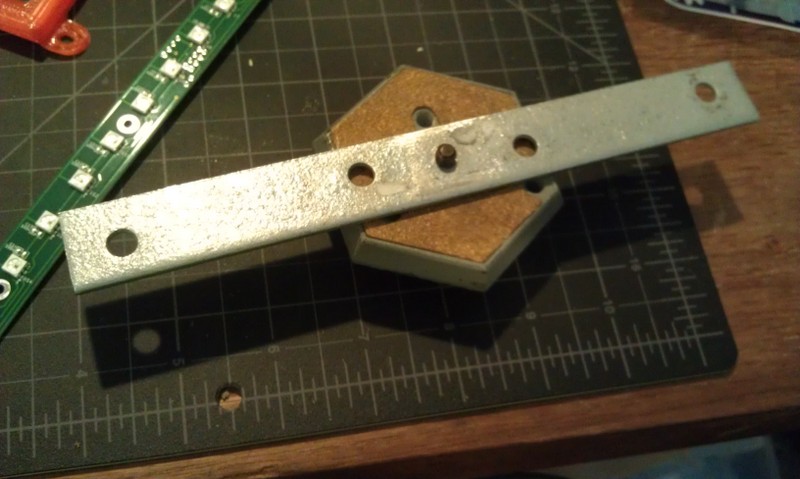
  • Proto-screw shield was too heavy and lifted off
  • Some of the nuts came loose in travel.
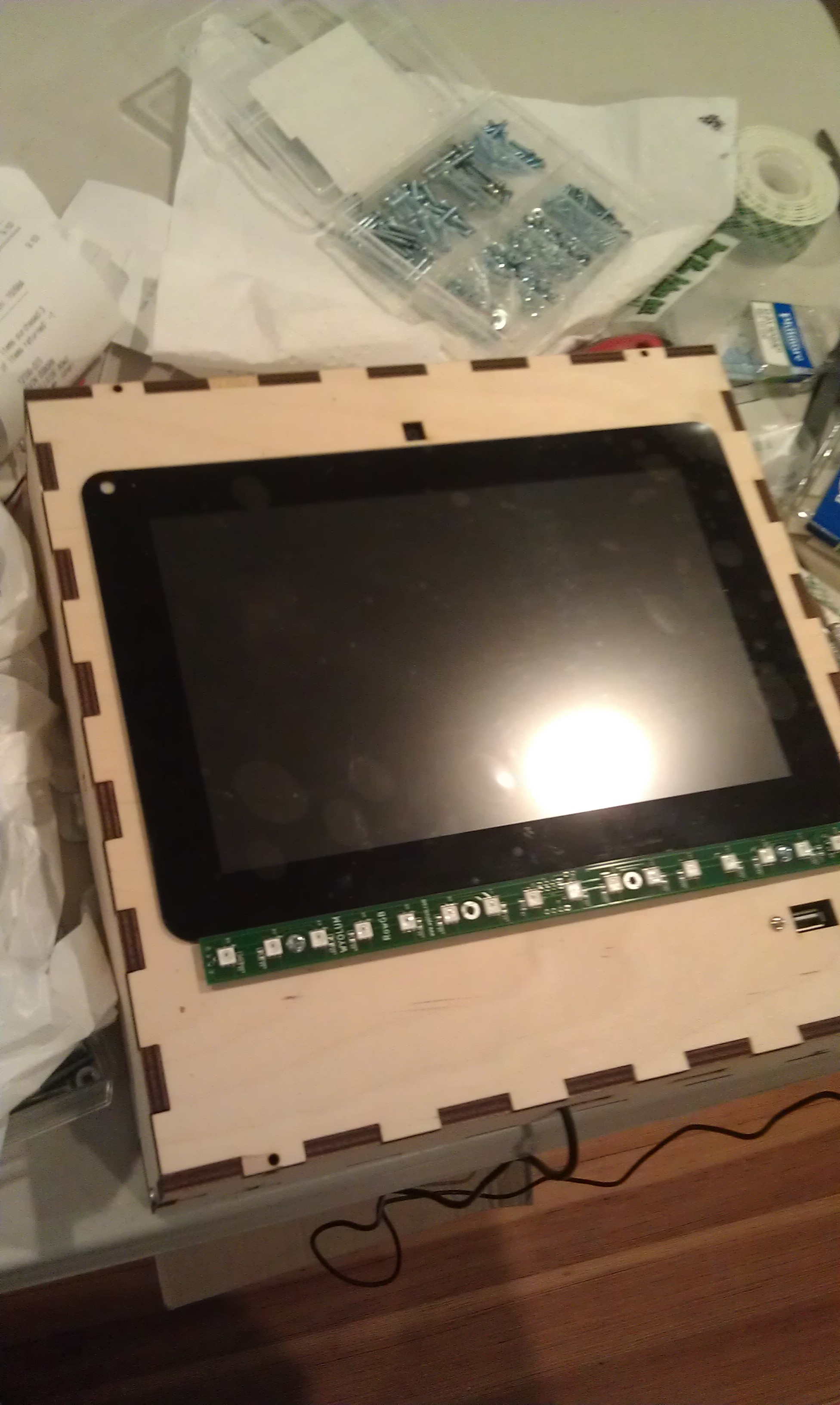
Photobooth 1.5

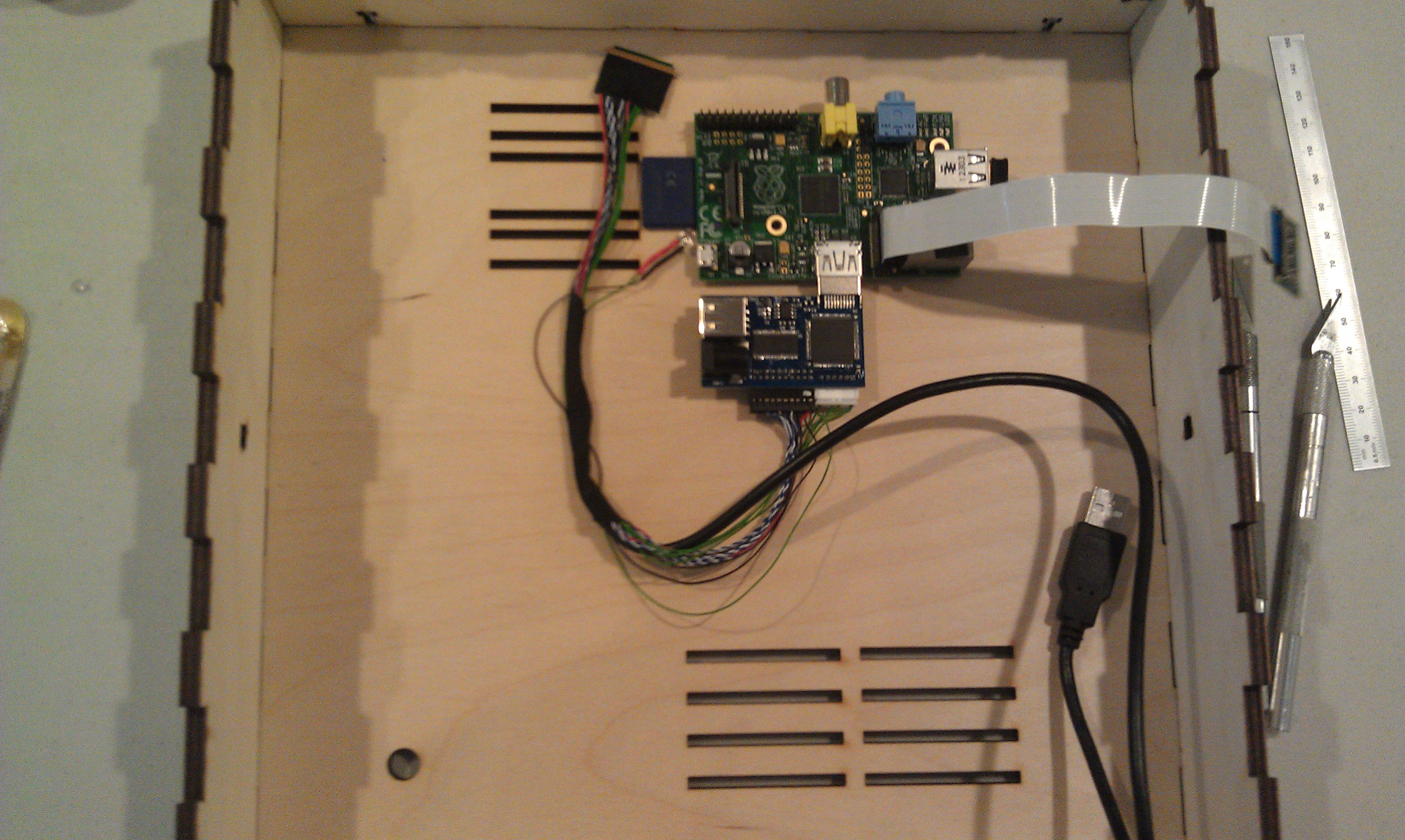
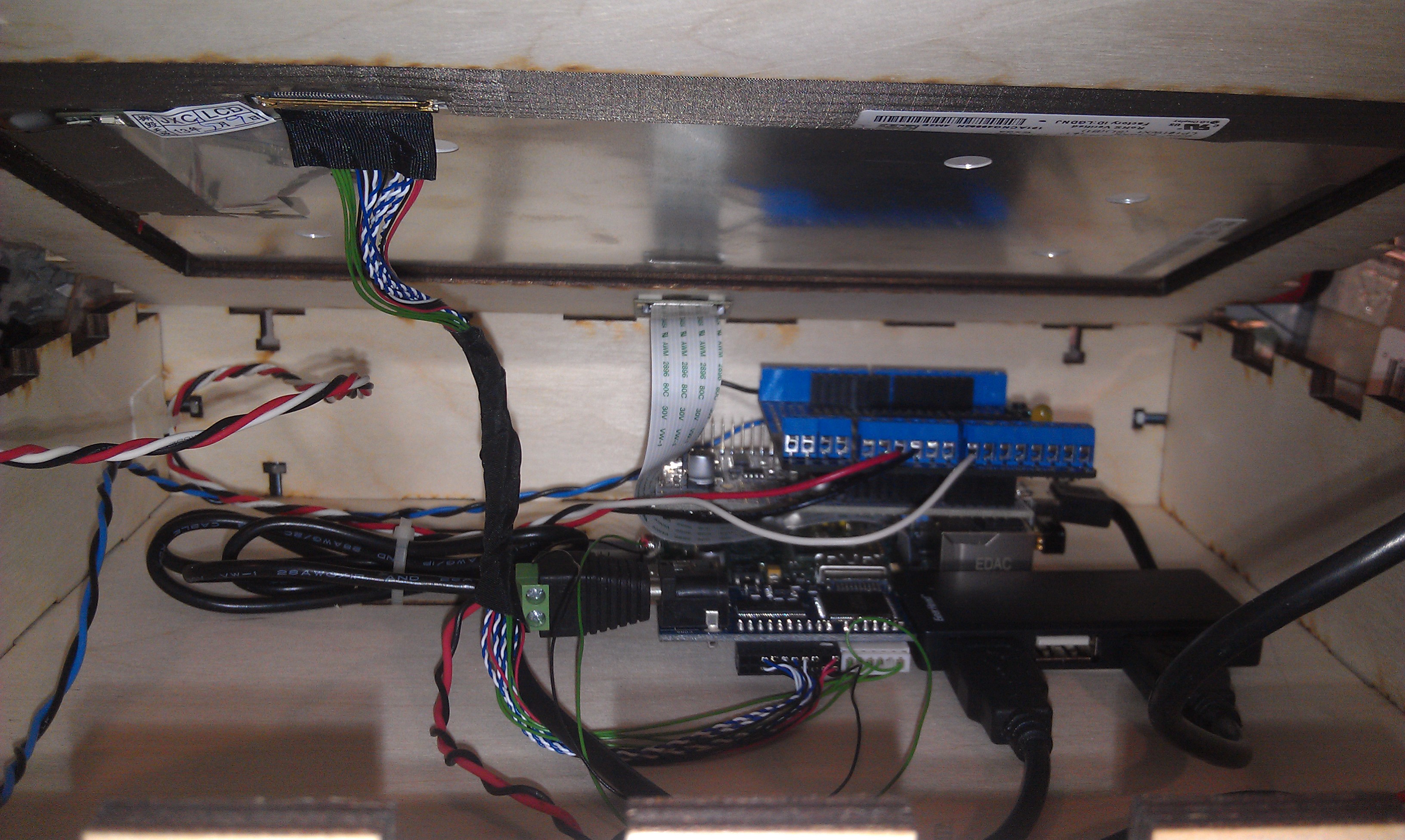
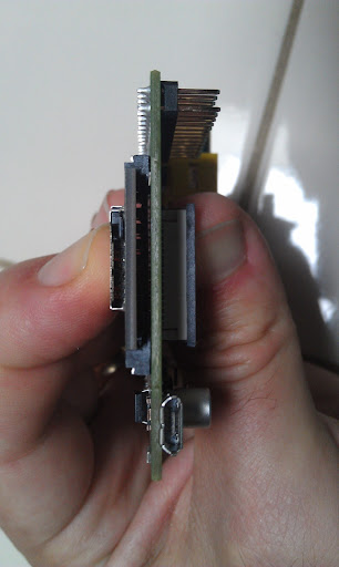
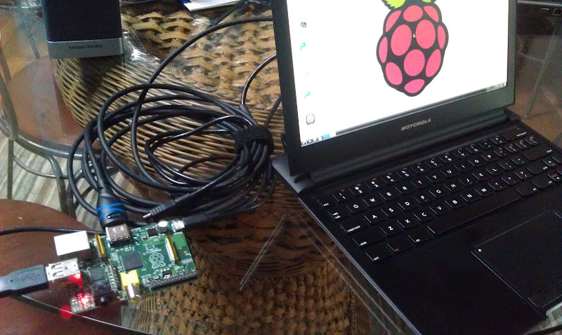
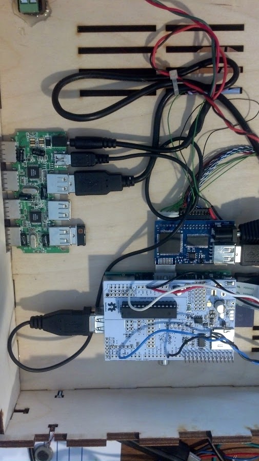
To solve the first problem, I determined to replace the non-powered hub in the photobooth with a powered one.  I tried to add power to the unpowered hub, and this worked at first, but then took out the power supply and made the raspberry pi flakey too.

Scratch that, I ended up using a small belkin powered hub. I y-connected the power to it.
I noticed that  a convenient orientation put  4 ports right next to the edge,  so I cut a hole in the box to expose them.

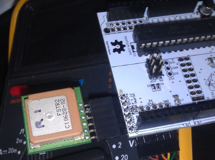
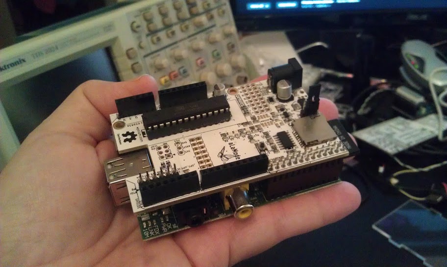
Luckily AlaModes ship without shield headers installed, so I replaced the AlaMode and protoshield with an AlaMode that was directly soldered to the button, led-strip, power and ground.

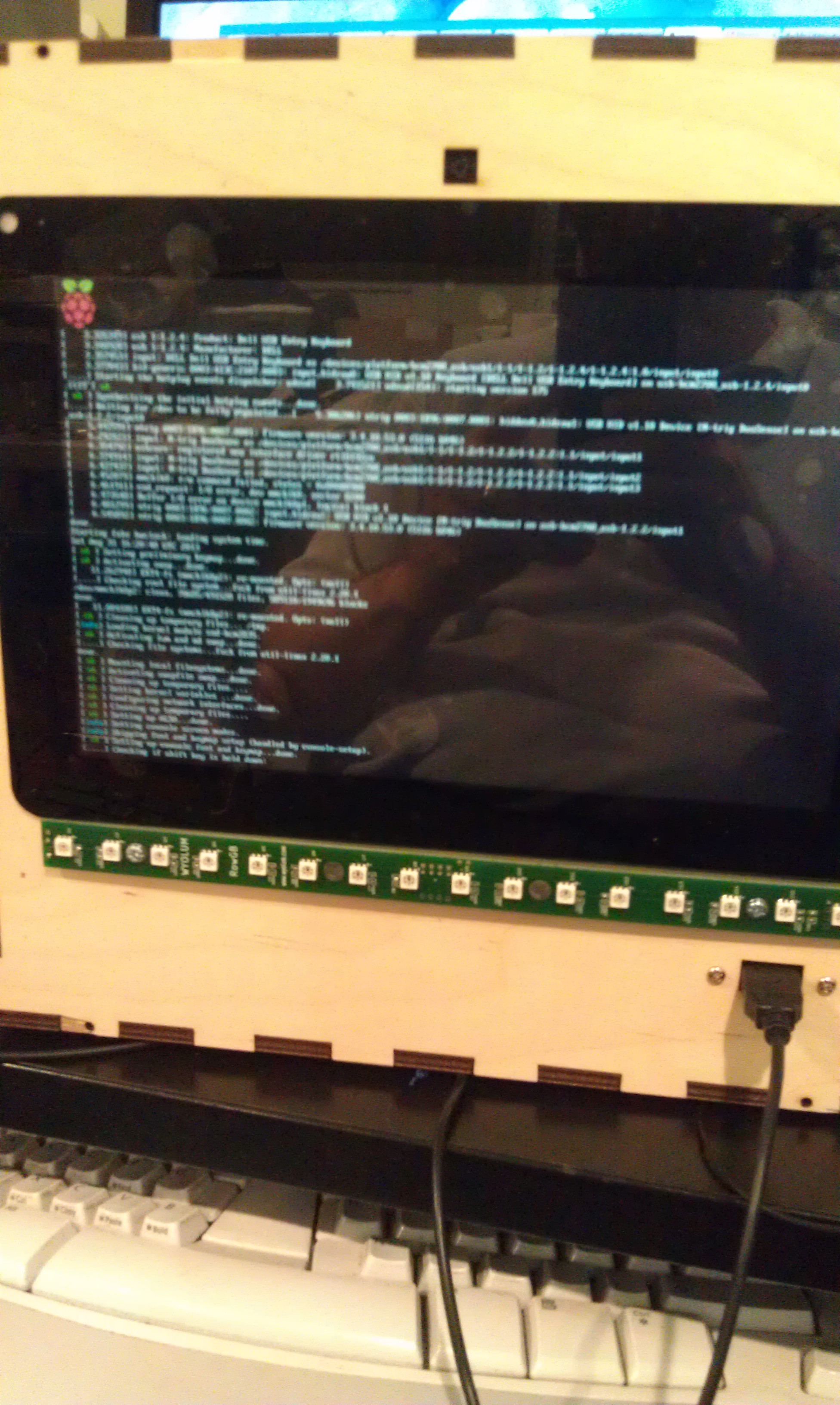
I updated the AlaMode’s photobooth program directly from the photobooth. Apparently the new AlaMode’s pullups weren’t as strong, so I added a 5.7k pullup to the Button Pin.


Open Hardware Summit Photobooth

As you know, my Wyolum buddies and I partnered up with SeeedStudios to make a really cool e-paper badge for the Open Hardware Summit which took place last week. We wanted some cool ways for people to customize their badges. Justin created a great simple program for converting images (wifit.py) and I leveraged that software to create a photobooth.

photobooth (by Addie Wagenknecht)
Photo by Addie Wagenknect

My friend Michael Castor at Makershed built a cool tablet from the Raspberry Pi, and he told me about the nice 10.1″ LCD display and HDMI adapter he found from Chalk-elec.

I ordered one, and started figuring out how to put the whole thing together. I also got a big red button from Adafruit. I have been playing with the Raspberry Pi camera and it’s perfect for embedding in a project like this, even though the software is a bit primative at this point (no video for linux drivers, etc.) I used our own AlaMode to read the button and use one of our WS2811 arrays to do a visual countdown before taking the picture.

I’d never really designed anything for laser cutting, and this was my opportunity! I used Inkscape, with the T-slot extension written by Justin. I got the box cut at Einstein’s Workshop (a family oriented makerspace in Burlington, MA.)

Lasercut box

Next, I laid out the components. The trickiest parts were the LVDS cable (though it’s pretty generous) and the Raspberry Pi Camera flex cable.

One really sweet thing about the Chalk-elec hdmi adapter is that you power it, and there’s a USB power port to power the Pi.

Raspberry Pi and HDMI adapter


Attaching the LCD to the case is a little nerve wracking, as like most tablet screens, it’s intended to be glued in. I used 3M permanent mounting tape (really not tape but adhesive on a backing roll.) It’s really difficult to cut with scissors (it sticks to everything) I made the mistake of putting it on the bezel and trying to cut it with an X-acto knife. I scratched the paint on the bezel, but I managed to fix it with a sharpie.

The better approach turned out to attach it to the opening, and cut along the opening.

IMAG1720-001

After trimming I added the LCD, and the USB panel mount jack.

I had to drill a few holes because I hadn’t completely planned ahead, for a jack for the switch box (used a 1/4 phone jack and plug) power, and the 16 pixel LED array.

IMAG1726


I had planned for it to swivel on the sides from two carriage bolts with wing nuts. This meant making a stand, and I didn’t want it to be just a couple of 2×4’s. Also I was running out of time so I took Justin’s suggestion and made a tripod mount for it. More holes…. And a mending plate from the hardware store. Fortunately I have a set of cheap taps from Harbor Freight, so it was pretty simple to drill the plate and tap it (1/4-20) to accept a tripod mount.

IMAG1730

Getting it hooked up with the short cables is a little tricky, but there’s room to get your hands in there:

IMAG1732I

I used a proto-screw shield to make it easier to hook up the button and LED leads. As you can also see, there’s a small usb hub inside too.

I booted it up:

IMAG1727


and then hacked Justin’s Wifit program to take a picture:

IMAG1728

Justin then created a more kiosk-y gui, and I ironed out a few things with the Arduino code for AlaMode. The gui checks to see if an sd card is mounted, and when it is, it sends an enable command to the button and prints on the screen “Press Button when ready”  The AlaMode then monitors for the button, and when pressed, sends the signal to take the picture and begins counting down on the LED strip. You can find the code in our github repository: https://github.com/wyolum/EPD

I tried also using the LED strip as a flash, and it worked but made sort of ghastly underlighting like a camp flashlight! So I took some cheap chinese led strip I had around (about $12 for 5 meters) and made a light panel:

IMAG1753

And the finished product:

IMAG1745

And on the badge:

IMAG1729I’m thinking of modifying the code to upload higher res pics to the Internet with an imprint, or printing them on a portable printer I picked up at a yard sale!

By the way, I left the Raspberry Pi’s wifi dongle attached, as it made it much easier to debug with SSH from my laptop. That said, I did also plug another hub into the one exposed port to use a keyboard and mouse (even though the touch screen does work!) If I had to do it over again, I might bring at least one more port out for other devices.

You’ll notice in the first picture, the Wyolum Logo across the top. Elizabeth Shaw cut that for me and delivered it the morning of the OHS, and it fit perfectly!


Using GPS with AlaMode

We included a header for the UP501 GPS module on AlaMode.
The UP501 is popular, and has the additional advantage of having a PPS output which can be used to do ultra-precise timing.

Unfortunately we made a little mistake and reversed the silkscreen on the connector (documented in this forum article.) The actual orientation is actually quite logical the RX pin of the GPS lines up with the corner of the AlaMode.

Mikal Hart wrote a wonderful GPS library called TinyGPS
http://arduiniana.org/libraries/tinygps/

The GPS library doesn’t actually talk to the GPS module, but parses the output (NMEA statements) In this case, our example code uses the SoftwareSerial library (also by Mikal Hart!) to listen for the output and feed it to the GPS library.

The pins used in AlaMode are 6 (receive on the Arduino, output from the GPS), and 4 (Transmit on Arduino, input into the GPS module.) Note you shouldn’t actually write to the GPS module from the Arduino, as it’s a 3V module, and the Arduino’s outputs are 5V. It is, however safe to read.
SoftwareSerial nss(6, 4);

also in the setup() function initalize the SoftwareSerial for 9600 baud:
nss.begin(9600);

After that, you are good to go! Stay tuned, in a future post, we’ll have a guest blogger who will be using the GPS feature of AlaMode to build a compact WarDriving module.

Here’s a copy of the GPS example code, pre-edited for use with AlaMode:


CNC AlaMode

AlaMode is in stock and shipping now from Makershed and SeeedStudios.

I’m a maker, and as a maker, I love tools. As a computer geek, I’ve long been interested in computer controlled tools. When Riley Porter of Synthetos suggested using AlaMode to control a CNC router from a Raspberry Pi, I was thrilled!

Riley and Alden Hart of Synthetos.com have been developing controllers for DIY CNC machines, and they make the controller for the Shapeoko, the lowest cost DIY CNC router around. They sent me the grblShield that is normally shipped with an Arduino in the complete Shapeoko kit.

I ordered the mechanical kit from Inventables.com, and then picked up stepper motors and a power supply from some surplus outlets.

This is of the simplest and most rewarding applications of AlaMode. People often dedicate an old computer to their CNC routers, but being in a dusty environment, it can be hard to keep everything running well. By stacking the credit card sized AlaMode, the Raspberry Pi and the GRBL shield, you get a wonderful networked platform for CNC that can be neatly boxed (though I haven’t gone that far yet!)

After assembling the Shapeoko, and wiring the motors to the grblShield, you’ll need to program GRBL onto AlaMode. Download the GRBL  optimized for GRBLShield, and assuming you’ve set up Raspberry Pi with the AlaMode version of Arduino, you can program it directly from the command line:

[code]avrdude -c alamode -b 115200 -P /dev/ttyS0 -p m328p -U flash:w:grbl-Shapeoko.hex[/code]

In the next post, I’ll talk about sending jobs to the AlaMode Shapeoko, including over the network!


AlaMode: Web controlled train example

Update!: You can now buy AlaMode at Seeedstudios

Here’s an example of using the AlaMode with the Raspberry Pi.

We had a great time demoing the AlaMode at MakerFaire. We got invited to demo in the MakerShed, because …. Surprise! MakerShed is going to carry AlaMode!

For this demo,  I took an adafruit motorshield and used it to modulate the power to a 9V Lego train track.

Photo by Brian Kronz

The Arduino code is pretty simple, using Serial.read to interpret single characters as commands for controlling the motor shield. “f” means forward, “b” means back, “s” means stop. 1-9 sets the speed.  You’ll also need to install the AFMotor  library.

Program the aalegotrain.ino sketch from here: https://github.com/wyolum/alamode/tree/master/examples/train_demo

You can either do this with an FTDI cable on another computer, or directly with the Arduino IDE on the Raspberry Pi.

The ala-modey part of this is to use the AlaMode to do the controlling motor bit. The Raspberry Pi will control the train through a web interface.

Install  lighttpd on the Pi (sudo apt-get install lighttpd) and put the web files from the example into /var/www.

photo by Drew Fustini

It’s a little slow because it’s a simple CGI script (spins up a whole process with each request.) A python script interprets button presses on the web page, and uses pyserial to send the characters to AlaMode.

Drew Fustini of Element 14 did a great blog post on our demo.

Here’s a video he posted:

[youtube]http://www.youtube.com/watch?fv=y-9g_mfdFhc[/youtube]

If you have any questions, join the conversation at the Wyolum forums.

Repairing Raspberry Pi SD holder

Do a quick Google, and you’ll find a lot of people have broken their Raspberry Pi SD card socket. Justin Shaw and I both broke ours within 15 minutes of each other while chatting on the Internet. In my case, I put my finger on the card while unplugging the HDMI cable.

The plastic is very brittle on the SD card holder of the Raspberry Pi. This one broke off on the right side when it was dropped with a card in place.

Adafruit makes a nifty half length Micro-SD to SD slot adapter. If I had this to begin with, my slot probably wouldn’t have broken. When I saw it, I thought maybe I could glue it in to restore function to the broken Pi. Phil Torrone of Adafruit graciously sent me one to try. (Warning: It’s hard to fix this slot, and hard to find a replacement, so I really had little to lose, but it would also be easy to mess things up further. If you don’t fix your Pi, and end up with a glued in sd adapter you can’t use, I’m not responsible!)

There’s a gap between the bottom of the “Card” and the PCB, so we’ll need a space filling glue that sticks to fiberglass

I happen to have some 5 minute epoxy that I purchased on a trip to Japan. It has glass in the pictures, so I figure it will do.

I always get a little nervous at this step.  Mix according to instructions. Equal amounts of the two parts. It sets up in 5 minutes but you should leave it overnight before applying too much force.

Glue and Clamp. I put some along the edges of the socket (make sure you don’t get it on the contacts) and then placed the adapter, and dripped some in to the gap. You should probably wait over night. While it’s pretty solid in 5 minutes, it may not be totally bonded/cured for 24 hours.

Ok, I couldn’t wait overnight. after about 10 minutes I tried it. Hack Successful!

he finished project. You can’t use SD cards anymore, but micros are pretty easy to come by, and it no longer sticks out for you to apply leverage.


Simplified Setup for Arduino on Raspberry Pi

I just got back from the Open Hardware Summit and World Maker Faire. It was fantastic and I spent a day and a half doing demos of Alamode and the Raspberry Pi in the Makershed. I’ll have more on that later, but I got a lot of questions about setting up Arduino, and I realized that things have been simplified since my last blog post on the subject.

I recommend you download the latest raspbian (these instructions are for that version.)

2012-09-18-wheezy-raspbian

After running through the setup (raspi-config) which runs automatically the first time do a:

[code]$ sudo apt-get update
$ sudo apt-get install arduino[/code]

You used to have to get the avrdude and gcc packages separately and install them in an unzipped version of arduino, but there’s now an up-to-date package. This works out of the box with FTDI Arduinos, but Uno’s /dev/ttyACM0 and the Raspberry Pi /dev/tty/AMA0 aren’t recognized by the Arduino IDE. To do that we create some “udev rules” that create symbolic links to those devices that are named /dev/ttyS1 (uo) and /dev/ttyS0 (alamode) respectively.

I created a setup script to do the hard work for you (note the $ represents the command prompt, don’t type that!):

[code]$ wget https://github.com/wyolum/alamode/blob/master/bundles/alamode-setup.tar.gz?raw=true -O alamode-setup.tar.gz
$ tar -xvzf alamode-setup.tar.gz
$ cd alamode-setup[/code]

If you want to be ready to run Alamode, and the Uno run:

[code]$ sudo ./setup[/code]

which disables logging and getty on the internal serial port (so you can use it to program alamode), sets up the /dev/tty links, and installs a modified avrdude that has a new programmer type, -c alamode. This should be completely safe, as I only and (I think properly) added a new programmer type, but I haven’t tested it thoroughly on other programmer types. It also sets up the board type for alamode in the Arduino IDE.

reboot to get rid of the logging and getty.

If you just want Uno support, type:

[code]$ sudo arduino-setup[/code]

Here you probably don’t have to reboot, just

[code]$ sudo udevadm trigger[/code]

If you want Bonjour, which will allow you to refer to your raspberry Pi on the local network as raspberrypi.local

[code]$ sudo apt-get update
$ sudo apt-get install libnss-mdns

[/code]

Arduino Setup instructions for Raspberry Pi

These instructions are for setting up an Arduino and alamode friendly environment on the Pi. Gathered from many sources (see earlier posts) and updated with the latest info.

Download and install Linux Image

Download the Black Raspberry Distribution from Adafruit:
http://learn.adafruit.com/adafruit-raspberry-pi-educational-linux-distro
DIrect link to the current (0.2 version):
http://adafruit-raspberry-pi.s3.amazonaws.com/Occidentalisv02.zip

Burn to your favorite sd card. Helpful tips at:
http://elinux.org/RPi_Easy_SD_Card_Setup

If you need to set up Wifi, or other things, follow the instructions at the first link above.

Configure your keyboard and Timezone

It’s difficult to edit config files when the quote key produces a different symbol.
Unless you are in or have a Great Britain keyboard, you’ll need to:

[code]sudo dpkg-reconfigure keyboard-configuration
sudo dpkg-reconfigure tzdata[/code]

Reboot

Serial Port configuration

AlaMode can communicate via the UART pins of the GPIO connector. Unfortunately, for now, the Arduino IDE doesn’t recognize the device name /dev/ttyAMA0, so you’ll need to create an alias. By the way, it also doesn’t recognize the Arduino UNO (/dev/ttyACM0) so you can handle this the same way.
[code]

sudo vi /etc/udev/rules.d/80-alamode-rules

KERNEL==”ttyAMA0″,SYMLINK+=”ttyS0″ GROUP=”dialout”
KERNEL==”ttyACM0″,SYMLINK+=”ttyS1″ GROUP=”dialout”

[/code]

Next, disable logging messages:
This bit disables logging to the GPIO UART, so if you are using an Arduino via USB, it’s not necessary.
[code]Edit /boot/cmdline.txt
From:

dwc_otg.lpm_enable=0 rpitestmode=1 console=ttyAMA0,115200 kgdboc=ttyAMA0,115200 console=tty1 root=/dev/mmcblk0p2 rootfstype=ext4 rootwait

to:

dwc_otg.lpm_enable=0 rpitestmode=1 console=tty1 root=/dev/mmcblk0p2 rootfstype=ext4 rootwait[/code]

deleting the two parameters involving the serial port /dev/ttyAM0
You also have to edit /etc/innitab to remove the login (getty)
comment out:

[code]2:23:respawn:/sbin/getty -L ttyAMA0 115200 vt100[/code]

Reboot

Installing the Arduino IDE

Before getting any of the other packages:

[code]sudo apt-get update[/code]

and again:

[code]sudo apt-get update[/code]


The IDE is written in Java (based on Processing) and while Oracle doesn’t have an official Java for the ARM core in the Pi, the Open JDK has been ported. It doesn’t have a JIT (Just In Time Compiler) so it’s a little slower, but it works.
First grab the Arduino IDE code. 1.01 is heavily entwined with the native GCC toolchain, so is a lot more work and not recommended. For now, stick with 1.0.

[code]wget http://arduino.googlecode.com/files/arduino-1.0-linux64.tgz

tar zxvf arduino-1.0-linux64.tgz[/code]

The Arduino IDE is written in Java, but there are native parts to do compilation for the atmega328p  microcontroller. Fortunately those have also been ported:

[code]sudo apt-get install avr-libc

sudo apt-get install libftdi1

sudo apt-get install avrdude[/code]

Java:

[code]sudo apt-get install openjdk-6-jre[/code]

Serial support:

[code]sudo apt-get install librxtx-java[/code]

And then copy the native stuff into the Arduino directory:

[code]cd arduino-1.0

for i in $(find . -name “librxtxSerial.so”) ; do cp /usr/lib/jni/librxtxSerial.so $i ; done

for i in $(find . -name “RXTXcomm.jar”) ; do cp /usr/share/java/RXTXcomm.jar $i ; done

cp /usr/bin/avrdude /home/pi/arduino-1.0/hardware/tools/avrdude

cp /etc/avrdude.conf /home/pi/arduino-1.0/hardware/tools/avrdude.conf

[/code]

And probably reboot again, and then you should be good to go! Contact me on Google + and let me know how it goes!

Introducing Raspbery Pi à la mode

Our first prototypes are back, and working quite well! SeeedStudio fabricated the prototype boards and quickly sourced the parts.  The boards were of excellent quality. We ran into a few hiccups along they way, but Seeed Studio took care of them right away, and rushed to make up time.

If you haven’t been following, Anool Mahidharia, Justin Shaw and I from the Wyolum.com OSHW collaborative have been developing a stackable Arduino compatible for the Raspberry Pi.

While there are lots of emerging examples of interfacing hardware to the Pi, it’s just not as easy as the Arduino, and the Arduino already has hundreds of libraries for interfacing with motors, sensors, and displays. While you can always plug an Arduino into the USB port, but it’s not as neat and embed-able as a a GPIO interfaced board. You can write a program on the Pi in any language you want to control or monitor your Arduino application, making Internet integration and control super easy. In addition you can even program the AlaMode directly from the Pi.

Here are the features including a few extra goodies:

  • Flexible power. Can be powered directly from the Pi, standalone with a battery or wall-wart, or USB power. This is important if your shield takes more power than the Pi can provide or if you want to undock it for standalone operation.
  • Programmable via the Pi’s UART on the GPIO pins, or an FTDI USB-Serial adapter or ISP.
  • Header for connecting Fastrax UP501 GPS.
  • DS3234 Real time Clock. The Pi doesn’t have it’s own battery backed RTC. You can set a program in the AlaMode to report the time to the Pi via serial or I2C
  • Micro-SD card slot. Useful for datalogging, and big-memory  for your Arduino applications
  • Row of Servo Headers connected to the PWM pins with a configurable power and ground rail

We’re in limited Beta right now, but as soon as it’s thoroughly tested, we hope to produce them for sale as soon as we can!