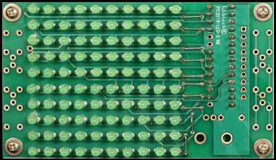
The family and I recently drove down to Providence, RI for the Mini-Maker Faire and Waterfire. It was really mini this year, but there were some good groups there including several hacker spaces and several of my favorite micro-businesses (mostly small electronic kit makers.) I’m usually inspired by something, but often too cheap to buy the really cool stuff. I bought two LED array kits from two different vendors, thinking it would be a good learning experience, both for myself and the kids. It’s also great to support local Makers! Also, I figure I’m contributing to open source by giving them feedback. John has already responded to the feedback I’ve given him and will be updating the site, and maybe even future designs (I thought he needed bigger solder pads…)
I bought two kits: a Charlieplexed 10×10 LED array from John Luciani (http://wiblocks.com) and an 8×8 LED driver based display from Modern Device. A charlieplexed display takes advantage of a quirk of microcontroller IO lines to control many LED’s with a smaller number of control lines. In the 10×10 display example, 11 IO lines are used. Since you only use the microcontroller and no additional chips, this design is much cheaper than the alternative. The disadvantage is that because it is multiplexed, the display will be dimmer and can’t really achieve full LED brightness when all the LEDs are lit. The driver version uses special LED driver chips that communicate with a serial protocol to use only 3 or 4 lines to drive many LED’s. In the Modern Device unit, it uses 4 chips (which share the same serial “bus”) each controlling 16 LEDs. Not only does this allow full brightness, the boards can be daisy chained together to make bigger displays, using the same control lines and a single microcontroller driving them.
I haven’t built the Modern Devices display yet, but I’ll share what I learned from the Wiblocks kit.

1. John is a really nice guy!
Ok, I already knew this as I’ve met him before at various maker events, but he was really generous as well, giving me a spare PCB for one of his drawdio remix boards (I have all sorts of EVIL plans for these! Stay tuned). He accidentally gave me the wrong board (an 8×8 board), so he promptly mailed me the right one and let me keep the other.
2. Read the instructions.

I admit I’m one of those guys who thinks winging it is better. One really cool thing about John’s designs is that he wants you to use them as a starting point, and makes them very flexible. The microcontroller board he includes with the kit is a mini version of the Arduino he calls the PICO1TR. He include instructions (and the appropriate components to build it to be compatible with 3.3V logic, or 5V logic.
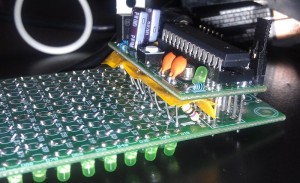
Since most of my past experiments have interfaced with 5V electronics, I built the controller as 5V, and then started the LED board and found out that with 3.3V you don’t need ballast resistors (not included.) Well, not a big deal, except my stock of resistors is all 1/4 watt, and the board is quite compact and laid out for 1/8 watt resistors. This meant they stick up, and I had to add some ugly insulating material to make sure I didn’t short things out.
3. Debugging!
There were a lot of LEDs to solder, and it’s really hard to keep them all neat and straight. Fortunately I learned that flux is my friend and the soldering went very quickly, and looks pretty neat. Some of the LEDs point this way and that, but I was in a hurry. The proper way to do this is to drill holes in a piece of wood or plastic, stick the LEDs in there, and turn the board upside down and solder in place. Like I said, I was in a hurry….
I installed John’s libraries and tried to download his sample code but it wouldn’t compile. It turns out that in one of the Arduino releases since John built his library, they included an new WinAVR which has different pin names. I changed all the PB0 etc. to PORTB0 etc. I then downloaded the program to the board, and Viola it worked! Well, mostly. There was an extra LED coming on sometimes in the blank area and when that LED was supposed to be lit, it didn’t and several other LEDs lit dimly. I wrote some test code:
Turns out, the LED was in backwards, and because of the way the charlieplexed LEDs are hooked up, some current leaks into the rows and columns around it. (I haven’t completely thought this through, so that may not be entirely technically correct…) I reversed the LED and everything is cool!.
[youtube]http://youtu.be/Mp_v50feMz0[/youtube]
4. Let’s write some code!
One of the excuses I used to buy this, was that I thought it would be good to teach about arrays. Now I haven’t been brave enough to try it on a kid, I did write a bunch of bitmap manipulation routines to set and query x,y values in the array. Hmmm, what do do with that? Conway’s Life of course! I’d never written that before, but it was fun, and made me think a little! Right now I have it set to randomly re-seed after a certain number of generations, but I’ve laid the groundwork to detect static displays, and the next version will run until the current generation is just like two generations back. Another thing I wanted to learn, but is in the future, is to post code on github, and I have an account there, but haven’t gotten around to posting it yet. Until then, here is my modified library, and here is my life code. Drop the library folder in the arduino/libraries folder, and the life code is an arduino pde file (add the folder to sketchbook folder).
[youtube]http://youtu.be/W44LtPPEcp8[/youtube]