Category Archives: kit reviews

Parametric Littlebits Mounting system

TL;DR version: I got to borrow the littlebits synth kit, and created a parametric version of the mounting board. The source files are available on github: https://github.com/osbock/Baldwisdom/tree/master/LittleBitsMounts

The Newton Free Library applied for and got a cool LSTA ( Federal Library Services and Technology Act) Grant to do a bunch of STEM related programs, and I have the honor of doing a bunch of coding and robotics workshops there over the next few months.

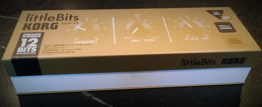
They got a bunch of cool new equipment to run these programs including Finch Robots, Arduinos (Sparkfun Inventors Kits), a KIBO robot, and … wait for it… a bunch of Littlebits sets. NFL Assitant Director Jill Grabowski was kind enough to lend me the coolest littlebits set: The Korg Synth kit.

korgset


If you aren’t familiar, they are modular electronics blocks that snap together with magnets. Unlike earlier “electronics construction sets” these are pretty foolproof, well thought out modules instead of just individual components. As Founder Ayah Bdeir says ,

AT LITTLEBITS, WE ARE ON A MISSION TO DEMOCRATIZE HARDWARE BY EMPOWERING EVERYONE TO CREATE INVENTIONS, LARGE AND SMALL, WITH OUR PLATFORM OF EASY-TO-USE ELECTRONIC BUILDING BLOCKS.

Unfortunately the thing that makes Littlebits easy is also it’s greatest weakness: The magnetic connection system.

Especially when making something you have to manipulate (like a musical instrument), they tend to come apart, you lose power, etc.

Now some of the other (more expensive) sets come with mounting plates (that you can also buy separately. I didn’t have one though, but I do have a laser cutter and a 3D printer. How hard could it be? Well, the devil is in the details.

First I looked to see if it was already done. Thingiverse (I know boo….) has a few designs, including some by littlebits themselves, mostly specific component mounts.

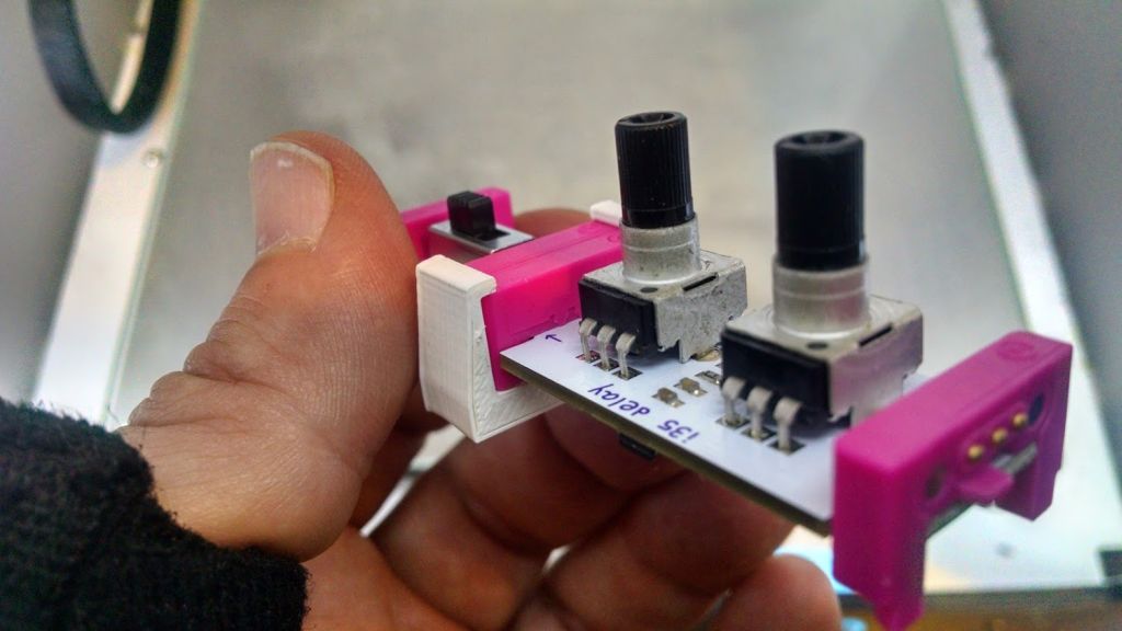
Rex Brodie posted this cool clip that fastens adjacent modules together.
clips

It works pretty well (very solid) but it was difficult to put the two bits in without pulling and pushing and putting a bit of strain on the boards. (Especially scary when the ‘bits are on loan).

I tried just measuring and cutting holes with my laser, or a simple model with Open SCAD but I just couldn’t get the spacing quite right.

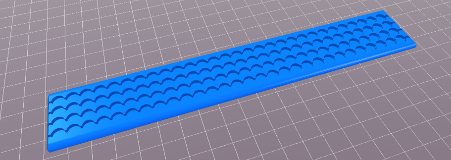
Thingiverse user Kris Kitchen had posted this design:
littlebitsgrid

which I printed and actually worked quite well. Only problem was, it was an STL (Surface Tessellation Layer) file, and thus not easily modifiable. I wanted wider, arbitrary shapes, etc!

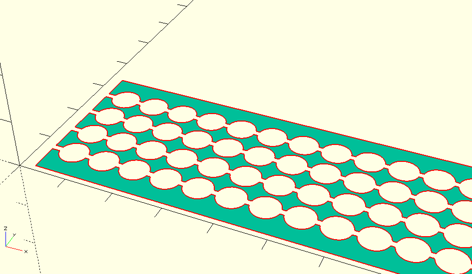
I could however pull Kris’s design into OpenSCAD, and do a trick to measure the “holes” and spacing.

This little bit of code:
[code]
projection(cut=false)difference(){
translate([0,0,-41])import(“LittlbitsGridthin.stl”);
translate([0,0,-10])cube([250,40,10]);
}
[/code]
cuts off the bottom so the holes will show and projects the outline in 2D.

projection

I then exported this as a DXF file, and used inkscape to make measurements.

If I haven’t lost you by now, the part you are waiting for, the measurements (which I couldn’t find anywhere after much googling!)

  • Holes: 6 mm diameter
  • Spacing (edge to edge or center to center): 6.63mm
  • spacing is also 10.5% of hole
  • 1.294mm knockout line

The percentage bit is important (I calculated it, 6.63/6) if you are designing in inkscape because that is how you do a grid of evenly spaced objects.

I made a couple of attempts at a laser cut version, but it was very brittle, and I didn’t take into account the laser’s kerf (width of cut)

The 3D printed version came out pretty well, but the holes were a bit too small, so I enlarged them by .2mm (.1mm on the radius). and it worked perfectly!
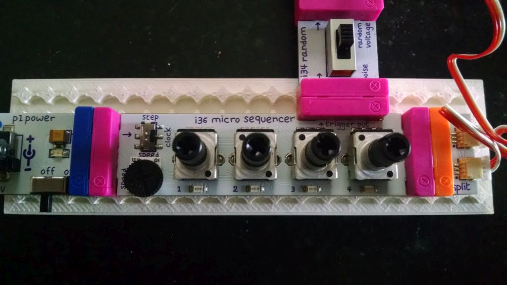
littlebitsmounted

Now we can make mounting boards in any shape!
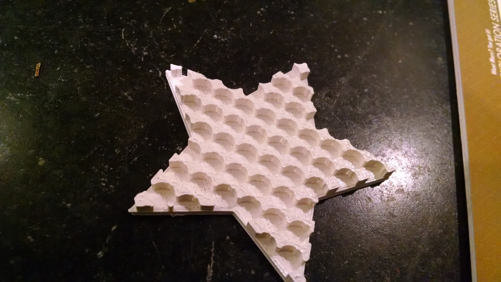
star

The source files are available on github: https://github.com/osbock/Baldwisdom/tree/master/LittleBitsMounts
3Doodler 2.0 First impressions

IMG_20150425_181802While it’s true that I love geeky new toys, I’m not typically an early adopter, preferring to wait until the bugs are worked out. Several of my neighbors got the first generation 3Doodler, and since it first came out, there have been many imitators. I backed the 3Doodler 2.0 kickstarter, and it arrived when I was away visiting family.

Impressions

It was a little annoying that it came via DHL with signature required. I managed to circumvent that via their website though, and it was nice to know ahead of time that I had a package coming.

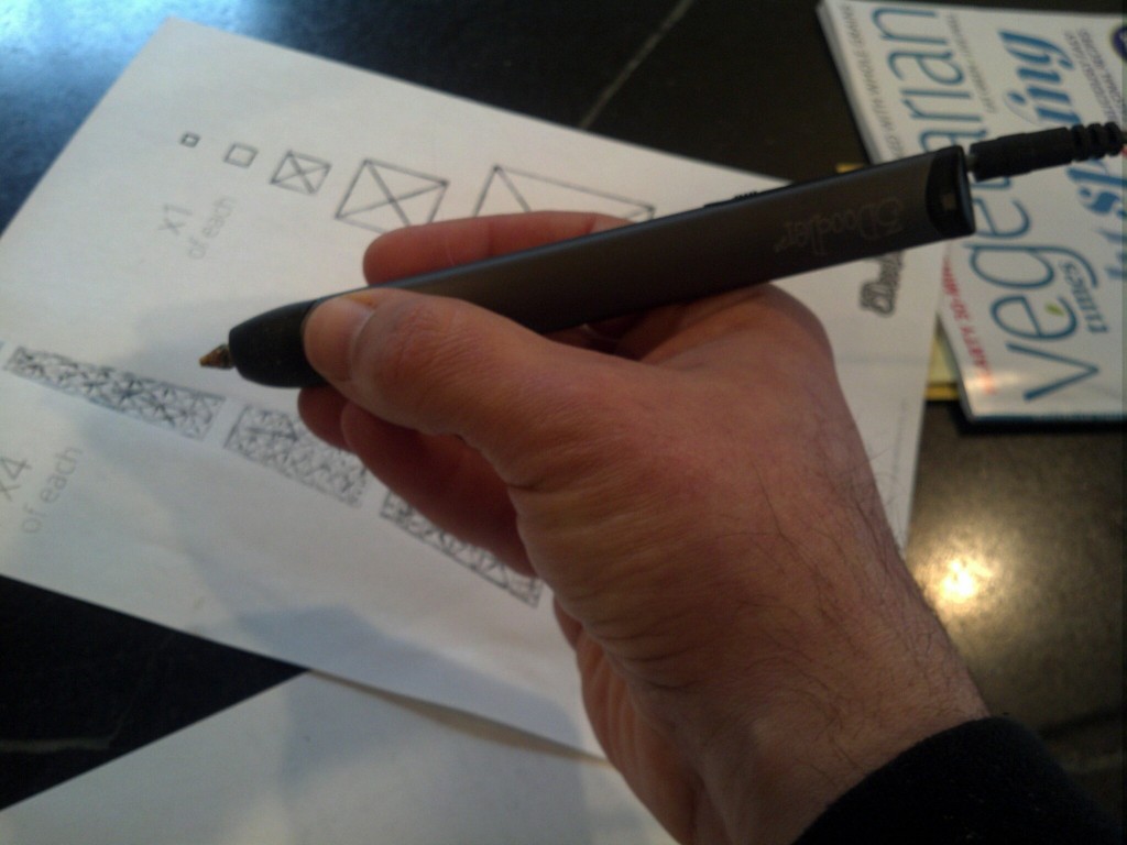
IMG_20150428_081610The new pen is Much Much sleeker and very pleasant to hold. I don’t have much experience with the first edition, but my impression was that it was clunky and it’s plastic case made me hesitate about spending $100 for an educational toy. The new design was a good part of what pushed me over the edge, and the metal case feels much more professional, and the mechanics seem to work really well. It comes with a little screwdriver to adjust the temperature, as well as a wrench to remove the nozzle and a cool spring thing to push through any unextruded plastic when changing colors.

Patience!

My 14 year old daughter initially almost threw it across the room in frustration. I think it was mainly a matter of expectations, as it does take a little while (after heating up) for a newly loaded strand to reach the nozzle. I also initially thought parchment paper (being heat resistant) would be good to doodle on, but it was a terrible choice as the plastic wouldn’t stick to it.

Doodling surface

We tried several other things, and eventually hit upon several good surfaces. It’s important not to doodle on a really cold surface (as our stone countertops are this time of the year in Boston) as the plastic shrinks quickly and comes unstuck. Some scrap acrylic worked really well, as did plain paper.

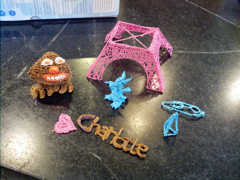
Once we had things humming along, Charlotte tried again and instantly did the cute baby dragon in the photo above. While it’s not a fast process, its quite meditative.

 3D vs 2D construction and materials

IMG_20150425_181857

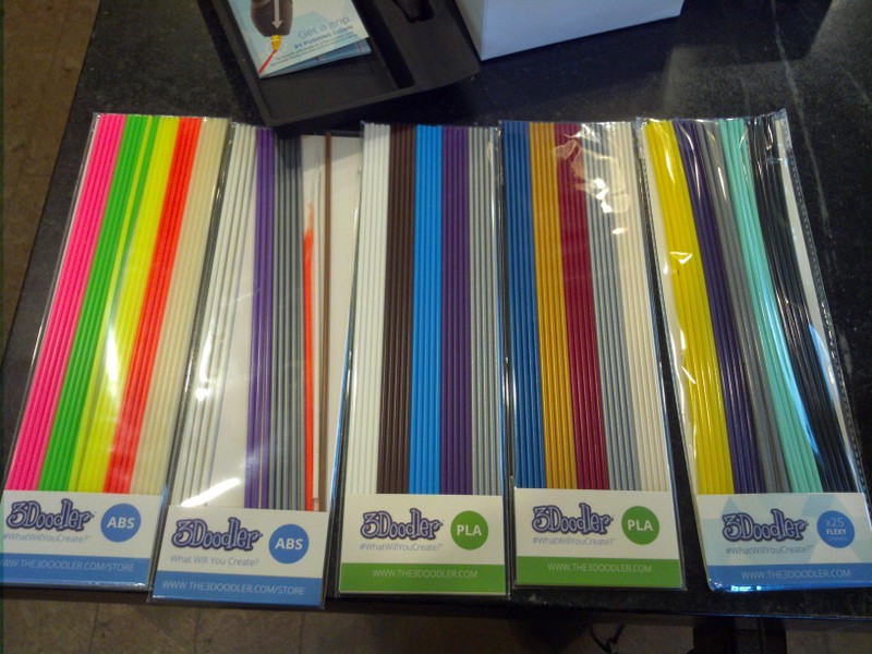
It comes with a nice variety of materials, 2 packs of PLA, 2 Packs of ABS and one pack of flexible filament. If you want to doodle in the air and make 3D objects in place, your only choice really is ABS as it hardens quickly. It would probably also benefit from a desk fan to speed up the process. You can do some vertical stuff with PLA by doodling upside down and let gravity hold things straight for you.

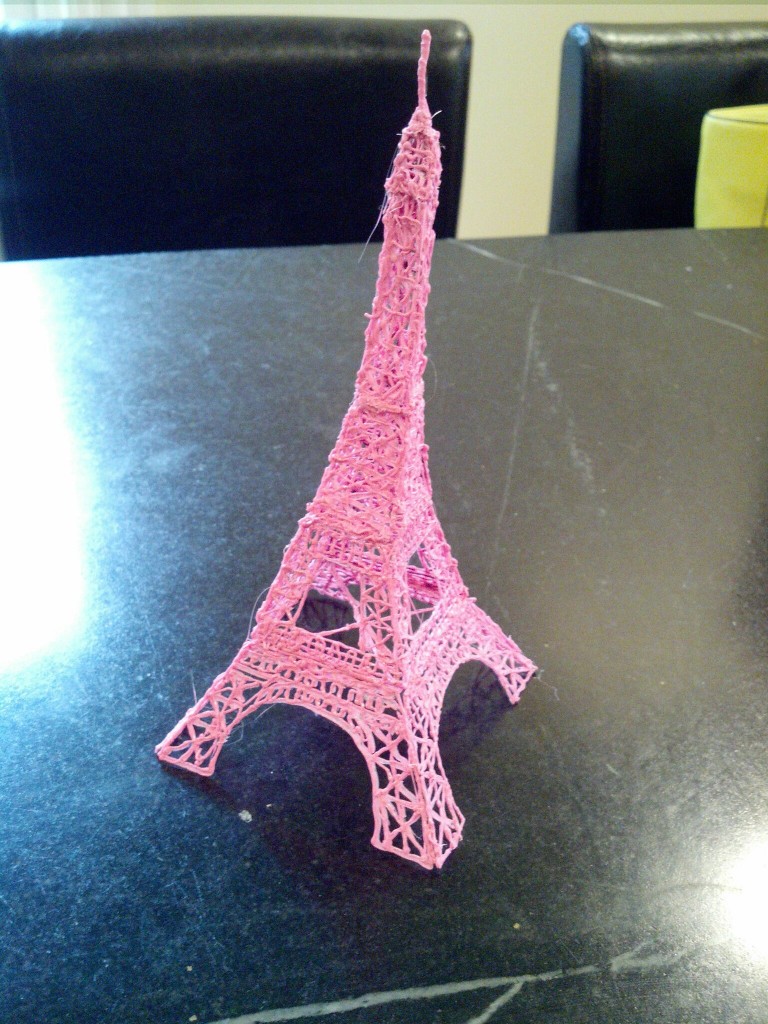
Another option is to doodle 2 dimensional parts and then tack them together with the pen. 3Doodler has a number of fun templates on their website that you can print out, doodle over then peel off and tack together. I did their classic Eiffel Tower.

IMG_20150428_081539

The first thing you’ll notice is that if you want precision, and a clean aesthetic, you should just get yourself a 3D printer. That said the drippy organic look has it’s own charm.

The second thing you’ll notice is that I made it from Pink PLA, and there certainly wasn’t enough of one color in the packs to do the whole thing. I’m fortunate to have a 3D printer that uses the same diameter (3mm) filament, so I cut some lengths of PLA. Because filament comes on a spool, the radius of the segments turned out to be a problem, causing it to not feed well. Holding the curvey segments over the stove burner (probably not recommended, a hair dryer would be a better choice). and rolling them straight on the counter made quite usable sticks that fed perfectly. There are two tools which are handy (and not included). One is a pair of tweezers to safely remove plastic from the outside of the nozzle,  and a pair of cutters to trim the melty part off the end of a filament you’ve backed out when changing colors.  They recommend you trim the end when reusing filament, but I managed to get the original sticks to feed in fine with little melty blobs on the end, but YMMV.

Accessories

I was already exceeding my budget to buy the pen, so I didn’t opt for any of the accessories, though I was sorely tempted. They offer a nozzle pack (including cool ribbony flat nozzles) and a battery pack for portable doodling. There’s also a foot pedal, whIch would relieve some of the stress of pushing the button (but I got pretty good at freehanding in the continuous extrusion mode…)

One other really cool thing they did for their kickstarter was to offer education packs that gave a good price with a generous helping of accessories for educational institutions.

Conclusion

I think the 3Doodler 2.0 is a well engineered and fun gadget. I’m planning on getting together with my neighbors and we’ll compare with the first version, as well as get more kid reaction, but in general I think it’s a great creativity inspiring tool.


TI MSP430 LaunchPad First Impressions

The DangerousPrototypes Blog had a quick post on a deal that Texas Instruments was offering a Watch/development kit for their low power processors for only $24. I’ll be telling you more about this in a future installment, but while I was grabbing the deal, I saw this neat little development kit for their low-power value-line processors. It cost all of $4.30, includes two processors and all the tools you need to get going.

First, while this is an extremely cheap USB enabled development board, this is NOT an Arduino. It is however, an excellent way to introduce yourself to real “on the metal” microcontroller programming.

I downloaded all the tools, and visited their site for pointers to example code, etc.

First, TI is really trying to do the community thing, with a wiki, and featuring other people’s content.

They also have a curated portal that has links to some really cool projects too at :

http://e2e.ti.com/group/msp430launchpad/w/default.aspx

They also have a really good, structured workshop with videos and labs to really give you an overview of the platform. So far, I’m about a third of the way through the workshop, and I’m really impressed so far.

Installing Code Composer studio took a long time. It needs work on it’s installer code, as it gave all sorts of scary warnings about User Account Control in Windows 7, but in the end it worked out fine.

This eclipse based tool is TI’s flagship micro development platform and is usually licensed for a $500 or more. This
free version limits you to 16 K of code, but that’s about the biggest device in the MSP430 value line.

It’s also really nice having hardware debugging support. No more Serial printlns! Set breakpoints and examine variables. Awesome!

These processors feature super low power features. In fact the other thing I bought, the chronos watch development platform uses the same line of processors. I won’t go into all the modes here (covered very well in the workshop) but these processors know how to sip power! We’re talking microwatts or less.

The MSP430 processors feature an extremely flexible clock architecture. This allows you to do all sorts of clever things, using different clocks for different parts of the chip, or even driving external circuitry. I’m just starting to wrap my head around all this, but it’s one of the cool things my fpga friends brag about, and now I can play too!

The Von Neuman memory map (single address space for everything) is much easier to use than the atmel’s harvard architecture. No more PROGMEM weirdness. Of course you still have to be ginger about writing to flash memory (constrained to write in blocks in self programming mode the same as AVR’s).

It has pretty advanced analog to digital conversion  with DMA, so you can set it up to transfer directly to memory. Not all the chips have this but many do, and some have fancy compariters to use for pid control, etc.

All in all, I’m very impressed. I think it will be a lot of fun, and a good learning tool. It really isn’t as easy as the Arduino, so I wouldn’t recommend it for “Toe dippers” or folks looking for a quick and easy automation tool.

If they keep offering it at this price though, it could be a great teaching tool. The processors (2!) it comes with are pretty small (both in IO and memory, 2K) so it will be hard to squeeze a lot of Arduino like library in there, but for some small teaching type challenges, it may be good enough, and you can always upgrade the processor for under $3.

A week later, I also ordered the CapSense booster pack, a shield to demo the chip’s built in (no additional hardware needed) ability to handle Capacitive  touch controls. I’ll probably post more about this once I’ve had the chance to play with it.

Soul-B-Gone: A super camera remote

I’ve had a lot of fun with my TV-B-Gone, which I bought direct from Mitch Altman (the inventor) at Maker-Faire RI a couple of years ago. I particularly like turning off the plague of flatscreens at work, and every one I can see through the glass doors in my building!

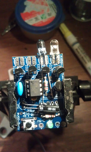
I have a Nikon D90, and the little IR remote which has been very useful, but is pretty weak. It’s flakey past 5 feet, and you really have to point it right at the front of the camera. I thought, gosh, the TV-B-Gone is AWESOME, and open source, so I set about to make it into a super Nikon remote.

Here’s the 1.2 kit from Adafruit. It’s more powerful because it uses a better design of cascading transistors.

The actual hack took less than a half hour. I found someone else had done the reverse engineering of the timing on the web (http://www.alanmacek.com/nikon/)

The 1.1 software was super easy to translate the timings to. I recently bought a version 1.2 kit (the current version) and ported the software which involved mostly changing the polarity of on/off, and using a single pin instead of two.

The biggest part of this project was assembling all the bits to program. I built a usbtiny (Love it…) and used an extra TV-B-Gone pcb as a minimal target board.

The thing is Awesome! I haven’t tested how far it goes, but it hasn’t failed me yet, and it bounces around any room I’ve tried it in to be far less directional.

Thank you Mitch and Limor! Your code was great, and it was such a thrill to make something I wanted!

You can download the firmware from github. Now the only problem is switching the chips. The 1.2 version frees up a pin to use as region select, so it is possible to use it as a switch to select between camera remote and tv-b-gone.

What Can You Learn From A Kit?

The family and I recently drove down to Providence, RI for the Mini-Maker Faire and Waterfire. It was really mini this year, but there were some good groups there including several hacker spaces and several of my favorite micro-businesses (mostly small electronic kit makers.) I’m usually inspired by something, but often too cheap to buy the really cool stuff. I bought two LED array kits from two different vendors, thinking it would be a good learning experience, both for myself and the kids. It’s also great to support local Makers! Also, I figure I’m contributing to open source by giving them feedback. John has already responded to the feedback I’ve given him and will be updating the site, and maybe even future designs (I thought he needed bigger solder pads…)

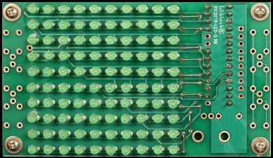
I bought two kits: a Charlieplexed 10×10 LED array from John Luciani (http://wiblocks.com) and an 8×8 LED driver based display from Modern Device. A charlieplexed display takes advantage of a quirk of microcontroller IO lines to control many LED’s with a smaller number of control lines. In the 10×10 display example, 11 IO lines are used. Since you only use the microcontroller and no additional chips, this design is much cheaper than the alternative. The disadvantage is that because it is multiplexed, the display will be dimmer and can’t really achieve full LED brightness when all the LEDs are lit.  The driver version uses special LED driver chips that communicate with a serial protocol to use only 3 or 4 lines to drive many LED’s. In the Modern Device unit, it uses 4 chips (which share the same serial “bus”) each controlling 16 LEDs. Not only does this allow full brightness, the boards can be daisy chained together to make bigger displays, using the same control lines and a single microcontroller driving them.

I haven’t built the Modern Devices display yet, but I’ll share what I learned from the Wiblocks kit.

Picture from John's site. Much nicer assembly than mine.

1. John is a really nice guy!

Ok, I already knew this as I’ve met him before at various maker events, but he was really generous as well, giving me a spare PCB for one of his drawdio remix boards (I have all sorts of EVIL plans for these! Stay tuned). He accidentally gave me the wrong board (an 8×8 board), so he promptly mailed me the right one and let me keep the other.

2. Read the instructions.

Ugh, could have avoided this!

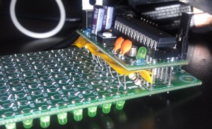
I admit I’m one of those guys who thinks winging it is better. One really cool thing about John’s designs is that he wants you to use them as a starting point, and makes them very flexible.  The microcontroller board he includes with the kit is a mini version of the Arduino he calls the PICO1TR. He include instructions (and the appropriate components to build it to be compatible with 3.3V logic, or 5V logic.
Since most of my past experiments have interfaced with 5V electronics, I built the controller as 5V, and then started the LED board and found out that with 3.3V you don’t need ballast resistors (not included.) Well, not a big deal, except my stock of resistors is all 1/4 watt, and the board is quite compact and laid out for 1/8 watt resistors. This meant they stick up, and I had to add some ugly insulating material to make sure I didn’t short things out.

3. Debugging!

There were a lot of LEDs to solder, and it’s really hard to keep them all neat and straight. Fortunately I learned that flux is my friend and the soldering went very quickly, and looks pretty neat. Some of the LEDs point this way and that, but I was in a hurry. The proper way to do this is to drill holes in a piece of wood or plastic, stick the LEDs in there, and turn the board upside down and solder in place. Like I said, I was in a hurry….

I installed John’s libraries and tried to download his sample code but it wouldn’t compile. It turns out that in one of the Arduino releases since John built his library, they included an new WinAVR which has different pin names. I changed all the PB0 etc. to PORTB0 etc. I then downloaded the program to the board, and Viola it worked! Well, mostly. There was an extra LED coming on sometimes in the blank area and when that LED was supposed to be lit, it didn’t and several other LEDs lit dimly. I wrote some test code:

Turns out, the LED was in backwards, and because of the way the charlieplexed LEDs are hooked up, some current leaks into the rows and columns around it. (I haven’t completely thought this through, so that may not be entirely technically correct…) I reversed the LED and everything is cool!.

[youtube]http://youtu.be/Mp_v50feMz0[/youtube]

4. Let’s write some code!

One of the excuses I used to buy this, was that I thought it would be good to teach about arrays. Now I haven’t been brave enough to try it on a kid, I did write a bunch of bitmap manipulation routines to set and query x,y values in the array. Hmmm, what do do with that? Conway’s Life of course! I’d never written that before, but it was fun, and made me think a little! Right now I have it set to randomly re-seed after a certain number of generations, but I’ve laid the groundwork to detect static displays, and the next version will run until the current generation is just like two generations back. Another thing I wanted to learn, but is in the future, is to post code on github, and I have an account there, but haven’t gotten around to posting it yet. Until then, here is my modified library, and here is my life code. Drop the library folder in the arduino/libraries folder, and the life code is an arduino pde file (add the folder to sketchbook folder).

[youtube]http://youtu.be/W44LtPPEcp8[/youtube]