Category Archives: hacking

Black Friday? No! F.A.T. Yes!

For the third year, our family entered in to the mad-crazy collaborative experiment that is  the Friday After Thanksgiving Chain Reaction at MIT in Cambridge. I think the main idea is to create, and not consume, and I love not only being there with my family creating, but also seeing the brilliant creations of everyone else.

As usual we weren’t super prepared (even th0ugh I spent most of the day on Thursday building) and spent almost till the last minute preparing and fixing, and our run wasn’t without the “Hand of God” helping it along, but it was fantastic!

I didn’t get very many pictures, but I’ll tell you about what we did.

The event is emceed by Arthur Ganson, artist in residence at MIT, and Mechanical genius. He has a whole room of his sculptures at the MIT museum, and it’s worth a trip just for that. He also generously helps people out, encouraging everyone, and builds the final link with some sort of theme. This year (the 14th) the theme was Sonnets, and his final piece dropped ostrich feathers one at a time with lines from a sonnet he wrote (it was beautiful!)

Each link is triggered either by a string pull or a golf ball entering your contraption. This year we decided to go for the additional challenge of the golf ball for the first time. We reused a ball run I made for last years event, and added an elevator for the ball made out of Knex.

Here’s the sequence:

  1. First the ball lands in a “chair” made out of Knex, and presses a Lego Mindstorms NXT touch sensor under it.
  2. This triggered the NXT to supply power to a short section of Lego 9V train.  The train steamed forward to…
  3. A brilliant Lego pneumatic switch mechanism design by our 11 year old neighbor and friend Jackson. This pneumatic contraption then fired his new high power laser pointer which….
  4. Popped a black balloon holding steel balls which
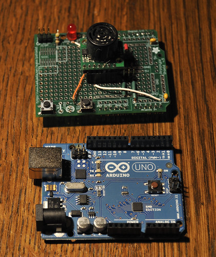
  5. Fell on a plate over a switch which triggered an Arduino controlled Silly String shooter. Getting to make this was some of the most fun. Before the event, I hooked it up to a motion sensor and surprised my kids with it. I got the idea while at Walgreens walking down the toy aisle. I thought, hey, I can probably rig a servo to spray that! Of course, googling it first, It’d been done! And cleverly too, so not one to reinvent the silly string shooter, I copied the design (though not the code…) Here’s the instructable that I used: http://www.instructables.com/id/Arduino-controlled-Silly-String-shooter/ by Instructables user Eric Kingston
  6. The silly string sprayed onto a paper plate (decorated as a target by Charlotte!) which pressed a microswitch that triggered another Arduino that used an Adafruit motorshield to run a KNex motor which I spliced into to run the winder to lift the golf ball. I use this shield a lot, for whenever I want to make some scavenged motor move something. For example I once built stuff from cd-rom drives for the kids to interact with in their classroom. Very handy.
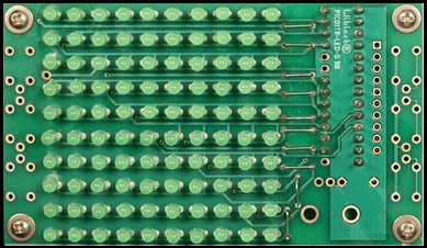
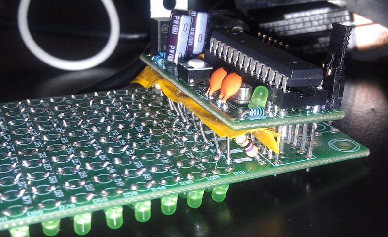
    When the golf ball reached the top…
  7. The same Arduino started spelling out a message on the super bright 8×8 LED panel from Modern Device that I picked up at Maker Faire in Rhode Island. It scrolled FAT.. This board has a fabulous library, is super bright, and really easy to use.
  8. The golf ball rolled down several ramps to a makeshift ramp between tables and on to the next table.

Our neighbors contraptions put ours to shame, both in terms of mechanical cleverness and overall finish. The one before us was an elaborate mechanism that shuttled brightly colored golf balls along a track to fall into a bucket, the weight of which eventually powered a putter to put the travel ball on to our section.

I encourage everyone to come and to build! It happens every year, and it doesn’t take much to participate (some links are little more than domino runs) and it certainly gets you away from the shopping crowds into a much better crowd!

Afterwards, we hung out in the empty gym and flew our new Air Swimmer (which I highly recommend!)

Woot! Free tool!

Instructables.com is one of my favorite sites, offering step by step instructions for all kinds of projects.

Instructables author Randofo created a cool Arduino shield for programming 8 pin attinys. In a brilliant move to get more instructables submitted, he offered one for free if you submitted an Arduino or AVR instructable. Well, that pushed me over the edge and I submitted my first one:

http://www.instructables.com/id/Turn-a-TV-B-Gone-into-a-super-camera-remote/

And this is what they sent me! Cool stickers and a badge! Now I just have to come up with a Nerd sash!As an added bonus, my instructable got featured on the home page and they rewarded me with a pro membership!

Now that’s the way to develop motivation to provide content!

Since getting the shield, I’ve already hacked it. It can’t program attinys with an external clock, so I added one, and put up this instructable:

http://www.instructables.com/id/Using-the-8Pin-ATTINY-programming-shield-with-an-e/

More Noise: Sound sample

I’m a little reluctant to release this, as the police may use it on the occupy protestors. This is one annoying sound!

It was pretty hard to hear what the circuit sounded like in the video, so I modified it to have a line level output and recorded it on my computer. At first I was baffled, as the volume kept going up and down, and there were weird compression artifacts until I figured out the  sound card in my computer was doing all sorts of noise reduction and signal processing on the microphone input! I turned it off and here’s the raw sound:

Making Noise, learning electronics!

I’d seen several projects on the net to make analog synthesizers, including the classic Atari Punk Console. I’m anxious to design something of my own, but I’m still learning, so I thought I’d start small. While this is not something that hasn’t been done before, I did it entirely from scratch. I read datasheets, and experimented with values for components.

Here’s a little video overview:

I did this project iteratively, first implementing a single oscillator controlled by a variable resistor or potentiometer. The capacitor I chose (220 pF) was somewhere in the middle of the range recommended by the data sheet, though I tried several other values. I have a cheap analog scope, and I could see the oscillation, but when I tried to attach a speaker, it went dead.  I hooked up a piezo element and it could drive that, but it wasn’t very loud. I stuck in a 2N2222 transistor, and used a pot to determine the optimal (loudest) bias resistor for the base, and replaced it with a fixed value.

Next, I replaced the pot with a photoresistor. This was fun, but the tone was pretty boring (plain square wave). I then hooked up another gate to drive an LED. Pointed at the photo resistor, but some distance away, it provides a cool beat, while the “average frequency is determined by the other light hitting the photoresistor. The frequency of the beat is controlled by a potentiometer like in the first circuit.

Here’s the schematic:

One tip: You’ll notice R3 in series with the potentiometer. This is because the pot goes all the way to zero, and at zero resistance the cap won’t charge and discharge properly setting up the oscillation. This sets some non-zero base value that you can set experimentally based on what you want that end of the frequency range to be.

Scary Robot Pumpkin Invasion

I left work a little early (around 4pm) to finish up the Cylon pumpkin.  The carving went pretty well, but it was starting to get dark by the time I put the electronics in.

If you want to do this project, please don’t do as I did with scratch building, and just buy the kit. When I put the electronics in the pumpkin, they didn’t work. I pushed my fingers around on the back of the board and I could get it to work sometime.

Back upstairs, I x-acto’ed between traces where there was already corrosion (I didn’t clean the flux very well) and resoldered a few things. Whew! Got it working 1 minute before the first trick or treater came!

[youtube]http://www.youtube.com/watch?v=QrUGX8nCOvk[/youtube]

And here’s the whole display. I hope you enjoyed it!

Desperate Halloween Project: The Cylon Pumpkin aka Larson Scanner

We’ve been so busy this season, there’s been little time for extra things. I used to go all out for Halloween, but this year we decided we couldn’t do much more than help the kids with their costumes. Well, this bothered me, and I decided to at least try to do a cool jack-o-lantern.

I’ve mentioned my love affair with EvilMadScientist.com before. They have a ton of quirky, always fun projects. (I’m still trying to convince Joyce we need an eggbot!)

They have a very nice, inexpensive kit to do a “Larson Scanner” which is  a row of LED’s that scan back in forth, like in the Glenn Larson TV shows Knight Rider, and Battlestar Galactica. They also love Halloween, and published a list of their Halloween related projects. The first Cylon Pumpkin they did, was a simple slit in the pumpkin to show off the scanner, but more recently they did this awesome carving:

The project linked to this picture uses an older circuit, not the EMSL kit...

Now I haven’t carved mine yet, and I wasn’t thinking ahead. It would have been much easier to just order their kit ($13) but I had most of the parts lying around, and I stayed up late laying it out and soldering it (badly) to a proto-board. My local electronics store doesn’t have a very good selection of proto-boards, but they had a cheap (<$3) proto-board laid out like a solderless breadboard.

I’m sure this is old hat to most folks, but I realized that I could squeeze the IC in, not in the middle where it’s supposed to go, but toward one side by cutting the traces between the rows of pins for the socket.

I didn’t want wires on the front, so I tacked them from the back, and that was hard, and a little messy, as it’s very cramped especially in the middle of the attiny micro.

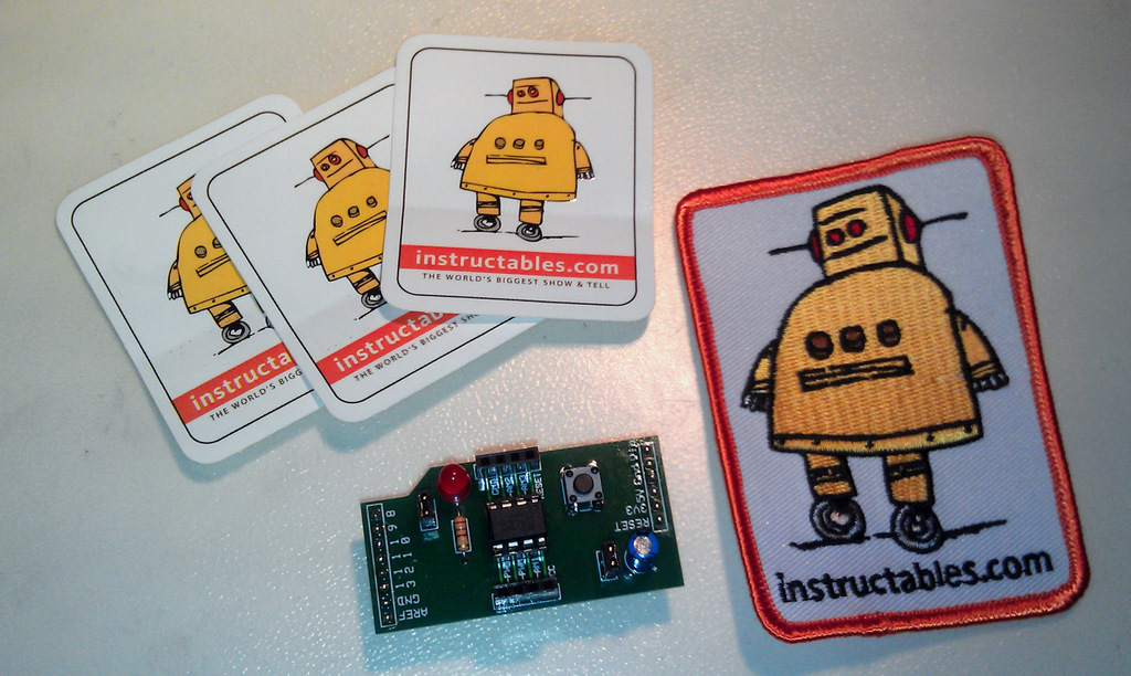
Once again, this whole project wouldn’t have been possible without my adafruit usbtiny ISP programmer. I used an Evil Mad Scientist minimal target board to program the chip.

EMSL’s code is a thing of beauty and a lot can be learned by studying it. Hopefully I’ll be back after tomorrow night with pictures of the finished Cylon-O-Lantern.

Soul-B-Gone: A super camera remote

I’ve had a lot of fun with my TV-B-Gone, which I bought direct from Mitch Altman (the inventor) at Maker-Faire RI a couple of years ago. I particularly like turning off the plague of flatscreens at work, and every one I can see through the glass doors in my building!

I have a Nikon D90, and the little IR remote which has been very useful, but is pretty weak. It’s flakey past 5 feet, and you really have to point it right at the front of the camera. I thought, gosh, the TV-B-Gone is AWESOME, and open source, so I set about to make it into a super Nikon remote.

Here’s the 1.2 kit from Adafruit. It’s more powerful because it uses a better design of cascading transistors.

The actual hack took less than a half hour. I found someone else had done the reverse engineering of the timing on the web (http://www.alanmacek.com/nikon/)

The 1.1 software was super easy to translate the timings to. I recently bought a version 1.2 kit (the current version) and ported the software which involved mostly changing the polarity of on/off, and using a single pin instead of two.

The biggest part of this project was assembling all the bits to program. I built a usbtiny (Love it…) and used an extra TV-B-Gone pcb as a minimal target board.

The thing is Awesome! I haven’t tested how far it goes, but it hasn’t failed me yet, and it bounces around any room I’ve tried it in to be far less directional.

Thank you Mitch and Limor! Your code was great, and it was such a thrill to make something I wanted!

You can download the firmware from github. Now the only problem is switching the chips. The 1.2 version frees up a pin to use as region select, so it is possible to use it as a switch to select between camera remote and tv-b-gone.

What Can You Learn From A Kit?

The family and I recently drove down to Providence, RI for the Mini-Maker Faire and Waterfire. It was really mini this year, but there were some good groups there including several hacker spaces and several of my favorite micro-businesses (mostly small electronic kit makers.) I’m usually inspired by something, but often too cheap to buy the really cool stuff. I bought two LED array kits from two different vendors, thinking it would be a good learning experience, both for myself and the kids. It’s also great to support local Makers! Also, I figure I’m contributing to open source by giving them feedback. John has already responded to the feedback I’ve given him and will be updating the site, and maybe even future designs (I thought he needed bigger solder pads…)

I bought two kits: a Charlieplexed 10×10 LED array from John Luciani (http://wiblocks.com) and an 8×8 LED driver based display from Modern Device. A charlieplexed display takes advantage of a quirk of microcontroller IO lines to control many LED’s with a smaller number of control lines. In the 10×10 display example, 11 IO lines are used. Since you only use the microcontroller and no additional chips, this design is much cheaper than the alternative. The disadvantage is that because it is multiplexed, the display will be dimmer and can’t really achieve full LED brightness when all the LEDs are lit.  The driver version uses special LED driver chips that communicate with a serial protocol to use only 3 or 4 lines to drive many LED’s. In the Modern Device unit, it uses 4 chips (which share the same serial “bus”) each controlling 16 LEDs. Not only does this allow full brightness, the boards can be daisy chained together to make bigger displays, using the same control lines and a single microcontroller driving them.

I haven’t built the Modern Devices display yet, but I’ll share what I learned from the Wiblocks kit.

Picture from John's site. Much nicer assembly than mine.

1. John is a really nice guy!

Ok, I already knew this as I’ve met him before at various maker events, but he was really generous as well, giving me a spare PCB for one of his drawdio remix boards (I have all sorts of EVIL plans for these! Stay tuned). He accidentally gave me the wrong board (an 8×8 board), so he promptly mailed me the right one and let me keep the other.

2. Read the instructions.

Ugh, could have avoided this!

I admit I’m one of those guys who thinks winging it is better. One really cool thing about John’s designs is that he wants you to use them as a starting point, and makes them very flexible.  The microcontroller board he includes with the kit is a mini version of the Arduino he calls the PICO1TR. He include instructions (and the appropriate components to build it to be compatible with 3.3V logic, or 5V logic.
Since most of my past experiments have interfaced with 5V electronics, I built the controller as 5V, and then started the LED board and found out that with 3.3V you don’t need ballast resistors (not included.) Well, not a big deal, except my stock of resistors is all 1/4 watt, and the board is quite compact and laid out for 1/8 watt resistors. This meant they stick up, and I had to add some ugly insulating material to make sure I didn’t short things out.

3. Debugging!

There were a lot of LEDs to solder, and it’s really hard to keep them all neat and straight. Fortunately I learned that flux is my friend and the soldering went very quickly, and looks pretty neat. Some of the LEDs point this way and that, but I was in a hurry. The proper way to do this is to drill holes in a piece of wood or plastic, stick the LEDs in there, and turn the board upside down and solder in place. Like I said, I was in a hurry….

I installed John’s libraries and tried to download his sample code but it wouldn’t compile. It turns out that in one of the Arduino releases since John built his library, they included an new WinAVR which has different pin names. I changed all the PB0 etc. to PORTB0 etc. I then downloaded the program to the board, and Viola it worked! Well, mostly. There was an extra LED coming on sometimes in the blank area and when that LED was supposed to be lit, it didn’t and several other LEDs lit dimly. I wrote some test code:

Turns out, the LED was in backwards, and because of the way the charlieplexed LEDs are hooked up, some current leaks into the rows and columns around it. (I haven’t completely thought this through, so that may not be entirely technically correct…) I reversed the LED and everything is cool!.

[youtube]http://youtu.be/Mp_v50feMz0[/youtube]

4. Let’s write some code!

One of the excuses I used to buy this, was that I thought it would be good to teach about arrays. Now I haven’t been brave enough to try it on a kid, I did write a bunch of bitmap manipulation routines to set and query x,y values in the array. Hmmm, what do do with that? Conway’s Life of course! I’d never written that before, but it was fun, and made me think a little! Right now I have it set to randomly re-seed after a certain number of generations, but I’ve laid the groundwork to detect static displays, and the next version will run until the current generation is just like two generations back. Another thing I wanted to learn, but is in the future, is to post code on github, and I have an account there, but haven’t gotten around to posting it yet. Until then, here is my modified library, and here is my life code. Drop the library folder in the arduino/libraries folder, and the life code is an arduino pde file (add the folder to sketchbook folder).

[youtube]http://youtu.be/W44LtPPEcp8[/youtube]

USB midi controller (Theremin style) on Arduino Uno

Creating Midi controllers with arduinos

Uno+shield

A warning to my non-technical friends: The following post is long and technically detailed. You might want to just check out the pictures and move on, but i’m hoping I can save a few people some hours of work by detailing everything I went through.

My son was interested in using a midi controller that used the distance your hand was above it to control his DJ rig with Ableton Live on his mac. I had done previous arduino midi projects with a midi shield from Sparkfun, but his mac doesn’t really have a native Midi interface. I found out that the midi standard now specifies a way of transporting midi over USB, and in fact most of the modern keyboard controllers, etc have this built in. Unfortunately. until recently, the USB interface of arduinos was a simple usb to serial controller chip that requires a driver, etc. People have written software drivers that convert between these (described here), but I felt that this was too complicated. There’s a commercial arduino-like clone that supports midi very easily (the Teensy) that I’ll talk about in a later post, because in fact, it’s actually a lot easier to use than what I ended up doing.
Arduino UNO to the rescue!

Instead of the USB-serial chip of previous arduinos, the UNO actually has a second microprocessor which is one of the USB enabled ATMEGAs, the ATMEGA 8U2. There’s even a bootloader in it that allows you to use Atmel’s DFU/flip protocol to load code.

Unfortunately, when I started, it was very difficult to figure out how to get this going, so I ended up trying to program the chip directly.

Making LUFA applications for the ATMEGA 8U2

A very cool guy who is very into ATMEL micro’s has written a wonderful library for just about every class compliant USB device to run on the ATMEGA processors. Dean Camera’s LUFA (Lightweight USB Framework for AVRs) can be found at Dean’s website; http://www.fourwalledcubicle.com/LUFA.php

One thing that wasn’t obvious to me in building LUFA applications is that the individual projects drive the build process. In other words if you do a top level build, and then drop down to your new project directory, you’ll get errors. So if you have already built LUFA, do a make clean at the top level, then cd to your project directory and do the make from there.

There are several good examples to start from and I wanted to make sure I could restore the UNO’s firmware, so first I built arduino-usbserial. This can be retrieved from the arduino repository or in the hardware/firmware directory of the arduino distribution.

The version distributed with Arduino-0022 seems to be incompatible with the latest version of LUFA(101122) but compiles nicely with LUFA 100807. Note that the following assumes you’ve already installed winavr (or the your platform’s equivalent)

  1. Download Lufa from http://www.fourwalledcubicle.com/LUFA.php
    Specifically I used:
    http://lufa-lib.googlecode.com/files/LUFA-100807.zip
  2. Copy arduino-usbserial from arduino-xxxxx\hardware/arduino\firmwares\ to the project directory of LUFA. In my case this is c:\LUFA 100807\projects
  3. cd to the arduino-usbserial directory you just made in LUFA and type make. Note I edited the makefile to use usbtinyisp for programming.

Getting the code on the ATMEGA8U2

There are two choices for loading the code onto the 8U2:

  1. Using the pre-programmed DFU bootloader. The instructions are now a little clearer, but still hard to find. Here’s the link.
  2. Soldering in the ISP header and using an ISP programmer such as Adafruit’s usbtinyisp I dried this first, and somehow bricked the usb part of the UNO. I can still upload code to either processor using USB tinyisp, but no USB goodness. I bought a smd version of the UNO which had the programming header in place and I was off to the races.

Moco lufa!

I was starting to look into the midi example in LUFA, but after several exchanged on the adafruit forums,  user morecat_labpointed to his project which is a very nicely done firmware for avr usb micros to do a serial to usb-midi conversion.

The MocoLUFA firmware (Thanks Yoshi!! (morecat_lab) works terrific, unmodified on my new SMD uno (which took forever to get here, by the way, grumble grumble)

First you need to download Moco for LUFA from Yoshi’s site: http://web.mac.com/kuwatay/morecat_lab./MocoLUFA.html

Since the existing Midi library uses the 328 serial port and the MOCA firmware relays those (repackaging them as USB messages), The midi code is trivial to implement. The only fiddly bit is that once you’ve reprogrammed the 8U2, you need to either restore it to load the 328 code, or use an isp programmer (which I recommend)

I still can’t get the hang of the DFU bootloading stuff (and the jumper pads seem to not be there for the SMD version), but fortunately the SMD UNO comes with the ATMEGA8U2 ISP programming header.

One detail that’s important: If you want to recompile the usb-serial firmware, you need an older version of LUFA, while the MOCO stuff compiles under the latest version. (Dean Camera apparently reorganized a lot of the headers which makes the application code incompatible without modification)
Here’s the version you need for MOCO:http://lufa-lib.googlecode.com/files/LUFA-101122.zip
To restore the original bootloader, you can either save out the contents of flash and restore it, or use one of the hex files in the arduino[xxx]/hardware/arduino/firmwares directory.

The MOCA interface loads automatically in Windows 7 (takes a while, but does configure) and instantly in MAC OSX

Theremin-like…

Well, a real theremin uses antennas and radio waves to modulate sound based on your hand position. I used distance sensors commonly used in hobby robotics. I made two version, one with the ultrasonic MAXBOTICS LV-EZ-1 which you can buy from Adafruit, Sparkfun, etc., and a Sharp IR sensor available from the same places. The Sharp IR version went into a box with a Teensy (which was kindof broken) so I’ll write about that later when I get the parts to finish it.

The Midi Bits.

The Maxbotics part is pretty easy to use. It has a proportional analog voltage output, RS232, and PWM. I hooked the analog output to one of the arduino analog inputs. The output is a bit noisy, and jumps around a little, so I resorted to a running average to smooth it out. This means I take several samples (configurable) average the last x number and report the mean of those samples.

Grant wanted midi CC (control change messages) to map to different music parameters (looping etc.) so I wired that in, however I didn’t have anything as fancy as his software, so for testing, I had it output note-on and note-off messages. I used a freeware program for windows called midi-ox