Category Archives: electronics

April Fools

About a week ago, Sparkfun posted a great prank in their weekly new product video. As April 1 was coming up, and I thought the kids would enjoy it, I ordered the bits that I didn’t have, and managed to pull it off.  Sparkfun didn’t give many details, so I thought I’d share my implementation.First here’s a video showing my wife getting pranked. She was a super good sport, (even not minding posting a video of her in her bathrobe!)

NOTE: Someone on google+ pointed out that at 8 amps, these horns could seriously heat up the li-po, and a hot li-po is not a good thing (fires/explosions!) so do this at your own risk. I only pulse the horns for 1 second at a time (twice per activation) so the battery never gets hot, but if you had a programming error, and it was stuck on, look out! Another good reason for the cutout switch and testing without the horns connected.

[youtube]http://www.youtube.com/watch?v=Hn6xDEUDoMw[/youtube]

Here’s what you’ll need for this prank:

  1. Arduino
  2. Accelerometer: I used this one from ModernDevices
  3. Digitally controlled relay. I used the same one they used in the Sparkfun prank
  4. The Horns!
  5. A (nearly) 12V lightweight battery. Sparkfun has this nice 1500 MAH 11.1 LIPO for a good price
  6. A compatible charger. Sparkfun recommends the IMAX B6 This can also be found on Amazon
  7. Wires, connectors, a good way to connect all the parts together

.

Here I wired the battery to power the Arduino, one leg of power went directly to both horns, and the other switched through the relay. I also put a toggle switch inline  with the power to the horns so I could shut off the horns for testing (The relay has an led and also clicks, so you can tell if it’s operating).

I had a proto-screw-shield on hand which was convenient for hooking up both the accelerometer and connecting to the relays.

Here it’s almost all hooked up. The relay connections are made to the analog side of the arduino to simplify wire routing. (Both 5V ground and io pins together.)

I use the button and LED on the protoshield to arm the device and indicate it’s status.

The bolts on the horns were too short to go through 1/4 ” plywood, so I used the supplied mounting plates to offset mount the horns.

Here it is all put together.  Here’s the Arduino sketch, but I recommend you try to program this yourself!

LCDBootDrive: Selectable Files!

New toy (o-o-o)

After I showed the BootDrive on the Adafruit Show and Tell, I watched their weekly “Ask an Engineer” show where they showcased a new product, an LCD shield with an RGB backlight. The really cool thing is that the LCD AND 5 buttons only need 2 IO pins on the Arduino, because the shield is designed with an I2C expander. I ordered it the next day (close to 5pm) selected UPS ground shipping and it was at my house the next day!

Here’s a quick video before I go through the blow-by-blow:

[youtube]http://www.youtube.com/watch?v=w5jPm3thkWo[/youtube]

I soldered the micro-sd breakout onto an Adafruit Proto Shield, and a 6 pin right angle header to connect an FTDI cable. Adafruit also had a pre-made 6pin-6pin female cable that was perfect for this project!

I wired it with fine wire-wrap wire on the bottom

The wiring is almost identical to the original BootDrive, except I changed the reset pin assignment:

Digital Pin5  –> FTDI Pin 6 (CTS)
GND                –> FTDI Pin 1 (GND)
Digital Pin1 (RX) –>FTDI Pin 4 (TX)
Digital Pin2 (TX)–>FTDI Pin 5 (RX)

SD Card Interface:
Digital Pin 10 –> SD-breakout CS
Digital Pin 11  –>  SD breakout DI
Digital Pin 12  –> SD breakout DO
Digital Pin 13  –> SD breakout CLK
GND                    –> SD breakout GND
5V                       –> SD breakout 5V

Debugging

I incorporated the directory listing code from the SD library examples, and instead of listing all the files, I did an openNextFile() each time the “down” button was pressed. It would be nice to be able to scroll up and down, but I’m pretty tight on memory as it is, so I didn’t want to cache the directory, or do some kludgy re-reading the whole directory to get to the file we are on.

The first problem I ran into was it worked fine until you scrolled through what turned out to be 25 names (actually the same 3 names 8+ times) and then it started repeating the same name over and over. When I realized it was always 25, I knew it wasn’t some overflow, and I finally figured out the example code had a bug in it! They list the directory by opening each file (with openNextFile() to get the name, but they never close it! If you try the listfiles example with more than 25 files on the card, you’ll see only the first 25. Easy enough to fix, as I’m scrolling I close the file after I get it’s name. I reopen it if you press the “select” or program button.

The next problem was a bit harder. The hex programs seemed to work on some boards but not others, even though there were apparently no errors. I created new test programs and suddenly they didn’t work either. Since the writing to flash seemed to be working, I figured that there must be some corruption of data. I read back the programmed AVR code from the target arduino (with avrdude  <programmer parameters….> -U f:r:readfile.hex:i) and compared it with the file I was sending to be programmed. It turns out I was advancing to the next “line” of 16 bytes even when I read less. Files that ended in shorter lines were getting placed ahead of where they needed to be and so the program was corrupt. Probably on some, the data that was already there was harmless, or the program didn’t actually execute that part of it’s memory, but in some cases it clearly was. Fixed, putback to github!

Have fun and let me know if you try it!

https://github.com/osbock/Baldwisdom/tree/master/LCDBootDrive

Precious Memory

There are two kinds of memory(well three including EEPROM, but we won’t deal with that here) you can run out of when doing an Arduino project (or any embedded project):

  1. Flash Memory: For a lot of applications, the Arduino has a fairly big flash memory (the UNO and all atmega328 based Arduinos give you 32k flash.) The Arduino IDE will also tell you if your program size exceeds the amount of flash in the particular Arduino you have selected.
  2. Static RAM: Atmega328 in the UNO gives you 2k of RAM. This is the most precious commodity in Arduino programming, and it’s often surprising how fast you can run out. The bad thing is,  the IDE won’t warn you, and your program can go from working to behaving really weirdly by doing something as simple as adding an additional debug print statement. This post will attempt to explain this, and give you a few tips for understanding your RAM use.

Where Did it All Go?
When you run out of SRAM, your program can just stop working, for reasons ranging from one data structure overwriting another (so your program does something based on the wrong value) to overflowing into the stack. When that happens, generally, your program dies a horrible death, because returning from subroutines can cause the processor to jump to random places in memory. If you make an innocuous change to your code (like adding another debug statement) and your program suddenly behaves very differently, chances are you have run out of SRAM.

It’s obvious if you declare large variable arrays like:

int valueArray[1024];

would instantly overflow memory because int’s occupy 2 bytes in atmega land. You also need to leave room for stack, and any other variables your libraries, and the Arduino software itself uses.

What’s Harvard got to do with it?
Not so obvious is the fact that:

Serial.println("Hello");
const char constantString[] = {"Hello"};

both  occupy 6 bytes in both flash memory and in SRAM (c-strings are terminated with a Null, or 0x00 byte).  The reason is AVR 8 bit microcontrollers use a Harvard architecture addressing scheme. This means that when an instruction addresses memory, there are two versions, one that addresses program memory (flash), and another to address RAM. Most routines like Serial.println use regular RAM, as they don’t know if you’ll be passing in constant info or stuff that you’ve constructed. As a result, even static strings (with a const declaration) are copied from flash to SRAM at system startup. It’s possible to write routines to only use flash (using the PROGMEM attribute) and it’s definitely useful, but that’s covered elsewhere.

I ran into this porting the avrdude stk500 routines to Arduino, blindly converting the printfs into Serial.print statements. In order to get enough RAM I ended up using numeric codes for errors (I’ll probably eventually get around to PROGMEM-ing them).

So, how do you tell if you are nearly running out, or have already? The IDE won’t tell you, so you have to dig in a little.

The build process for arduino produces an “ELF” file or Executable and Linkable File. This is used to create the actual HEX file for programming, but still has memory segment information embedded in it.

First find your build directory. On Windows 7 this is \users\<youruser>\AppData\Temp\build<a bunch of numbers>.tmp

Now, assuming you have the avrdude files somewhere in your path, use the command:

avr-size -C --mcu=atmega328p <yourelf-file.elf>

For example, the current version of Bootdrive gives me:

avr-size -C --mcu=atmega328p BootDrive.cpp.elf
 AVR Memory Usage
 ----------------
 Device: atmega328p
Program: 19272 bytes (58.8% Full)
 (.text + .data + .bootloader)
Data: 1340 bytes (65.4% Full)
 (.data + .bss + .noinit)

It’s probably best not to go beyond 95% full for your Data (that’s the SRAM part) to save room for your stack, and even less if you pass big variables on the stack or have deep call chains.

BootDrive for Arduino

Announcing the formal release of BootDrive for Arduino. If you’ve been reading the blog, you know that I’ve been working with Justin Shaw of Wyolum labs to enable their I2SD (Arduino clone with a micro-sd card) to bootload a program onto another Arduino. After battling several issues, mostly related to porting avrdude code to the Arduino (assumptions about infinite memory, etc!) it’s working well enough people can fool around with it.

Right now the code looks for a single file (“program.hex”) and waits 5 sec and then blasts it into the target arduino. Details about setting up to try this yourself follow the video.

Here’s a demo of it in action:

[youtube]http://www.youtube.com/watch?v=i4wJ4kRO80E[/youtube]

If you’d like to try this with a couple of Arduinos, you’ll also need an SD card (or micro-sd) interface such as the Adafruit Micro-SD breakout. This board is great because it has onboard 3.3v conversion so it’s safe to use with 5V (stock) Arduinos. Download the code from github: https://github.com/osbock/Baldwisdom/tree/master/BootDrive
or a zipped version here

Hook up your Arduinos like this:

I

The basic setup is:

Arduino Control:
Master Digital Pin6  –> Target reset
GND                                –> GND
MASTER Digital Pin1 –>Target Digital Pin2
MASTER Digital Pin2 –>Target Digital Pin3

SD Card Interface:
 Master Digital Pin 10 –> SD-breakout CS
Master Digital Pin 11  –>  SD breakout DI
Master Digital Pin 12  –> SD breakout DO
Master Digital Pin 13  –> SD breakout CLK
Master GND                    –> SD breakout GND
Master 5V                       –> SD breakout 5V

Optional debugging serial interface (This lets you see error messages and the like)
Master GND    –> FTDI cable Pin 1 (GND)
Master Digital Pin 4 –> FTDI cable Pin 5 (diagram is wrong, but you can change it in the code if you need to)

Here are the defines you can change to swap the pins around:

#define BOOT_BAUD 115200 // This is the Arduino UNO’s bootloader baud rate. Other boards are different!
#define DEBUG_BAUD 19200 // for software serial debugging
#define txPin 4
#define rxPin 5 // not really used…
#define rstPin 6

Also if you want to put your SD card on a different line (or are using a shield that uses a different chip select) change this:

const int chipSelect = 10;

Action!

Right now, 5 seconds after initialization, the program blasts a file called “program.hex”. You can add your own user interface to select amongst multiple programs.
Just call:

void programArduino(char *filename)

with the filename, e.g.”

programArduino("program2.hex");

You can build new hex files by grabbing them from the Arduino build directory. Make sure you have the IDE set up for your target board and press the “compile/verify” button.

From http://arduino.cc/en/Hacking/BuildProcess:

The .hex file is the final output of the compilation which is then uploaded to the board. During a “Verify” the .hex file is written to /tmp (on Mac and Linux) or \Documents and Settings\<USER>\Local Settings\Temp (on Windows). During upload, it’s written to the applet sub-directory of the sketch directory (which you can open with the “Show Sketch Folder” item in the Sketch menu)

Note on Windows7, the base directory is \users\<USER> \appdata\local\Temp\build<some bunch of numbers>.tmp\<sketchname>.cpp.hex

Note that if you want to load an Arduino other than UNO, you’ll need to change the baud rate. You can find that in “hardware/arduino/boards.txt” in the arduino directory. This won’t work on MEGA based Arduinos as they use the stk500v2 protocol (thanks westfw!)

Everything You Always Wanted to know about Arduino Bootloading but Were Afraid to Ask

Breaking through!

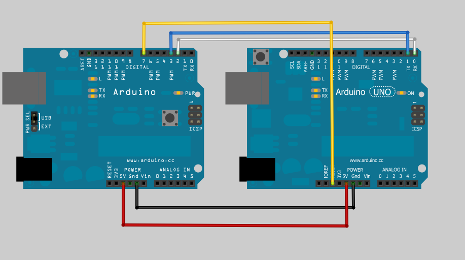
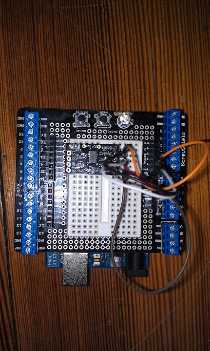
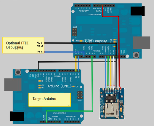
It’s been a while since the last update, but some progress has been made. I discovered that SoftwareSerial library doesn’t work really well at 115200 baud, so I switched the wiring around to use software serial for debugging, and the hardware uart pins (Arduino pins 1 and 2) to talk to the bootloader on the target. This is a little bit of a pain, as you have to unplug the connection to the target to download code to the “programmer” but it does work now.

I had a little trouble getting sensible responses from the bootloader until I put in a delay after resetting. In retrospect this makes sense as the AVRdude code reminded me that there are capacitors on the Arduino reset line. I was probably trying to talk too soon.

What bootloader, speed, protocol?

There have been several different bootloaders in the history of Arduino, and the source code for the current “canonical” loaders is included in the Arduino software distribution.  The bootloader is a little piece of code that allows you to program the flash memory of the Arduino’s atmega328p via serial or USB instead of using an ICSP programmer.  These bootloaders implement a subset of the STK500 8bit protocol (not to be confused with STK500v2) which is documented at www.atmel.com/atmel/acrobat/doc2525.pdf

Arduino MEGA (1280 and 2560) use yet another bootloader, one that uses the stk500v2 protocol instead.

The source code for the bootloader used by the diecimila, duemilanove, and a few other clones  is in …\arduino-1.0\hardware\arduino\bootloaders\atmega. Many clones use this, or a variant hacked by Lady Ada (Limor Fried).

The UNO and other later Arduino variants use a much smaller bootloader called Optiboot (more room for your code!). A little secret is that you can actually burn this bootloader into your older arduinos (at least at atmega168 and greater) and then just refer to the board as an UNO.

Adafruit Forum user westfw (one of /the?) author of  optiboot points out:

Optiboot also supports the mega8. However, you can only call a board an Uno if it at has a m328 cpu in it. For m8 and m168s with optiboot, you’ll need to make a new entry in boards.txt that copies the Uno bootloader parameters, but has the correct “build.mcu” specification (and fuses, if you want to program the bootloader using the IDE.)

The code for this is in …\arduino-1.0\hardware\arduino\bootloaders\optiboot. If you need to change the processor or baud rate, the settings are in the Makefile. This version is very stripped down, and doesn’t support, for example, writing to EEPROM. I’m choosing to use this as my initial target. Most of the code will still work on the older bootloader, but may require a slightly different command set.

The latest and greatest optiboot can be found at it’s Google code site: http://code.google.com/p/optiboot/

Which is also the preferred place for bug reports and to check for newer versions (atmega1284 is now supported!)

Because of varying clock rates, and different bootloader code, the various boards use different baud rates to talk to the IDE. This information is found in the …\arduino-1.0\hardware\arduino\boards.txt file. The UNO programs at 115200 baud, the Duemilanove (with ATmega328p) programs at 57600 baud. The Diecemila or Duemilanove with ATmega168 programs at 19200 baud.

Looking at the actual protocol

After the Arduino IDE compiles everything down to a intel hex file for downloading to the target Arduino, it uses the avrdude command to program the Arduino. The upload protocol is also specified in the boards.txt file and is called arduino, which is a slight variant of avrdude’s stk500 protocol. Most of the commands are from the stk500 module, except the signature reading is slightly different. For now, I’m adapting the avrdude code directly for the Arduino. This requires some minor porting (eliminating fprintfs, removing some of the indirection that links it to the avrdude programmer framework). I may simplify some of this code later as I’m a little nervous about running out of room.

As I mentioned in my last post, I downloaded a trial version of AGG Software’s Advanced Serial Port Monitor, and recorded the conversation between avrdude (controlled by the Arduino IDE) and the UNO target board. I stayed up late last night annotating the conversation:

DTR and RTS are both toggled from High to low several times

Avrdude then sends the GET_SYNCH command, thows away whatever comes back and sends it again a couple of times
Avrdude/Arduino IDE:#30#20 STK_GET_SYNCH, Sync_CRC_EOP
Target/Arduino UNO:  #14#10 STK_INSYNC, STK_OK
Avrdude/Arduino IDE: #30#20 STK_GET_SYNCH, Sync_CRC_EOP
Target/Arduino UNO:  #14#10 STK_INSYNC, STK_OK
Avrdude/Arduino IDE: #30#20 STK_GET_SYNCH, Sync_CRC_EOP
Target/Arduino UNO: #14#10 STK_INSYNC, STK_OK

Get the version number of the bootloader (in this case it’s 4.4) we could use this to branch to different variants of protocol.
Avrdude/Arduino IDE: #41#81#20 STK_GET_PARAMETER, STK_SW_MAJOR, SYNC,CRC_EOP
Target/Arduino UNO: #14#04#10 STK_INSYNC, 0x04, STK_OK
Avrdude/Arduino IDE: #41#82#20 STK_GET_PARAMETER, STK_SW_MINOR, SYNC_CRC_EOP
Target/Arduino UNO: #14#04#10 STK_INSYNC, 0x04, STK_OK

The next two commands are consumed but ignored (probably used by a real programmer to retrieve device specific stuff.)
Avrdude/Arduino IDE: #42#86#00#00#01#01#01#01#03#FF#FF#FF#FF#00#80#04#00#00#00#80#00#20(This is a STK_SET_DEVICE Command that is consumed but ignored by the bootloader)
Target/Arduino UNO: #14#10 STK_INSYNC, STK_OK
Avrdude/Arduino IDE: #45#05#04#D7#C2#00#20 STK_SET_DEVICE_EXT (also ignored)
Target/Arduino UNO: #14#10 STK_INSYNC, STK_OK

Enter Programming mode.
Avrdude/Arduino IDE: #50#20 STK_ENTER_PROGMODE, SYNC_CRC_EOP
Target/Arduino UNO: #14#10 STK_INSYNC, STK_OK
Avrdude/Arduino IDE: #75#20 STK_READ_SIGN, SYNC_CRC_EOP (read device signature)
Target/Arduino UNO: #14#1E#95#0F#10 STK_INSYNC, (three byte signature), STK_OK

The next four commands are consumed but ignored. I won’t bother to reproduce them in my code.
Avrdude/Arduino IDE: #56#A0#03#FC#00#20 STK_UNIVERSAL,0xA0,0x03,0xFC,0x00 SYNC_CRC_EOP (This is a pass through command that is supposed to be used to perform arbitrary native SPI commands. In this case, and the next 3, they are Read EEPROM byte commands They are consumed but ignored by the bootloader)
Target/Arduino UNO: #14#00#10 STK_INSYNC, (last byte written by the Universal command, STK_OK
Avrdude/Arduino IDE: #56#A0#03#FD#00#20 STK_UNIVERSAL,0xA0,0x03,0xFD,0x00,SYNC_CRC_EOP (Ignored by the bootloader)
Target/Arduino UNO: #14#00#10 STK_INSYNC, (last byte written by the Universal command, STK_OK
Avrdude/Arduino IDE: #56#A0#03#FE#00#20 STK_UNIVERSAL, 0xA0,0x03,0xFE,0x00,SYNC_CRC_EOP (Ignored by the bootloader)
Target/Arduino UNO: #14#00#10 STK_INSYNC, (last byte written by the Universal command, STK_OK
Avrdude/Arduino IDE: #56#A0#03#FF#00#20 STK_UNIVERSAL, 0xA0,0x03,0xFF,0x00,SYNC_CRC_EOP (Ignored by the bootloader)
Target/Arduino UNO: #14#00#10 STK_INSYNC, (last byte written by the Universal command, STK_OK

Here’s where we actually get started. This specifies the address in Flash where the follwoing PROGRAM_PAGE data goes.
Avrdude/Arduino IDE: #55#00#00#20 STK_LOAD_ADDRESS, 0x0000, SYNC_CRC_EOP
Target/Arduino UNO: #14#10 STK_INSYNC, STK_OK
And then the actual data. Note that the data is in the same order as the bytes in the Intel Hex file
Avrdude/Arduino IDE:
#64#00#80#46#0C#94#61#00#0C#94#7E#00#0C#94#7E#00#0C#94#7E#00#0C
#94#7E#00#0C#94#7E#00#0C
#94#7E#00#0C#94#7E#00#0C#94#7E#00#0C#94
#7E#00#0C#94#7E#00#0C#94#7E#00#0C#94#7E#00#0C#94#7E#00#0C#94#7E
#00#0C#94#7E#00#0C#94#9A#00#0C#94#7E#00#0C#94#7E#00#0C#94#7E#00
#0C#94#7E#00#0C#94#7E#00#0C#94#7E#00#0C#94#7E#00#0C#94#7E#00#0C
#94#7E#00#00#00#00#00#24#00#27#00#2A#00#00#00#00#00#25#00#28#00#2B
#00#00#00#00#00#20
STK_PROGRAM_PAGE, 0x0080 (page size), ‘F'(flash memory), data bytes…,SYNC_CRC_EOP
Target/Arduino UNO: #14#10 STK_INSYNC, STK_OK

And then we repeat – set address, program page, etc.
Avrdude/Arduino IDE: #55#40#00#20 STK_LOAD_ADDRESS, 0x0040, SYNC_CRC_EOP
Target/Arduino UNO: #14#10 STK_INSYNC, STK_OK
A
vrdude/Arduino IDE: STK_PROGRAM_PAGE, 0x0080 (page size), ‘F'(flash memory), data bytes….,SYNC_CRC_EOP
Target/Arduino UNO: #14#10 STK_INSYNC, STK_OK
.
.
.
Then it reads several pages (probably to verify what it wrote)

Avrdude/Arduino IDE: #55#00#00#20 STK_LOAD_ADDRESS, 0x0000,SYNC_CRC_EOP
Target/Arduino UNO: #14#10 STK_INSYNC, STK_OK 

Avrdude/Arduino IDE: #74#00#80#46#20 STK_READ_PAGE,0x0080 bytes, ‘F’ for flash, SYNC_CRC_EOP
 Target/Arduino UNO #14 STK_INSYNC
Target/Arduino UNO #14#10 STK_INSYNC, STK_OK
#0C#94#61#00#0C#94#7E#00#0C#94#7E#00#0C#94#7E#00#0C#94#7E#00#0C#94#7E
#00#0C#94#7E#00#0C#94#7E#00#0C#94#7E#00#0C#94#7E#00#0C#94#7E#00#0C#94
#7E#00#0C#94#7E#00#0C#94#7E#00#0C#94#7E#00#0C#94#7E#00#0C#94#9A#00#0C
#94#7E#00#0C#94#7E#00#0C#94#7E#00#0C#94#7E#00#0C#94#7E#00#0C#94#7E#00
#0C#94#7E#00#0C#94#7E#00#0C#94#7E#00#00#00#00#00#24#00#27#00#2A#00#00
#00#00#00#25#00#28#00#2B#00#00#00#00#00 

#10 STK_OK

repeat several times at different addresses

.
.

And then leaves programming mode
Avrdude/Arduino IDE: #51#20 STK_LEAVE_PROGMODE, SYNC_CRC_EOP
Target/Arduino UNO #14#10 STK_INSYNC, STK_OK

Then we’re done! Avrdude then toggles DTR/RTS to reset


Detour: From Auto-programmer to Serial Boot drive

When I originally posted about the Auto-programmer I was pleased to see several people on my Google+ stream and in the Adafruit forums were interested. Justin Shaw of Wyolum labs was interested in the idea of reading the program off the SD card, but instead of programming a microcontroller chip directly, program another Arduino compatible (specifically one of his gorgeous clocks!)

He’s already made an Arduino compatible SD card reader board he calls I2SD (it speaks I2C) that also speaks TTL serial, so it would be perfect. 
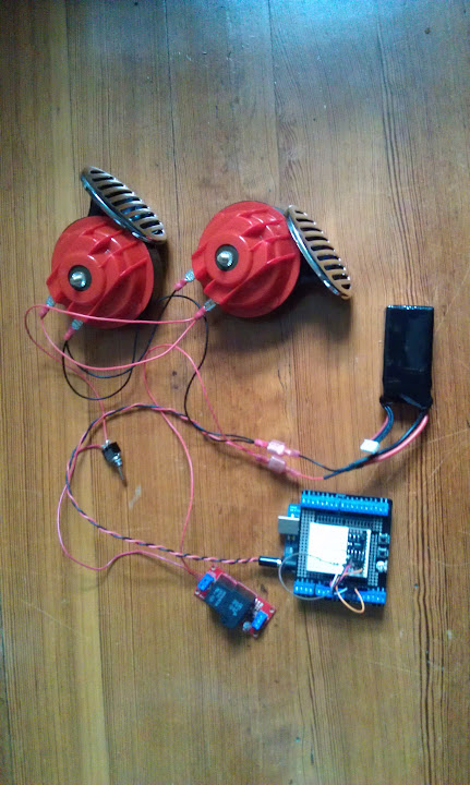
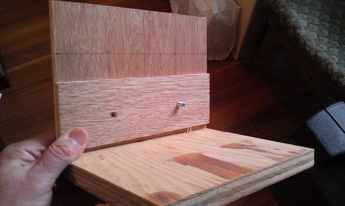
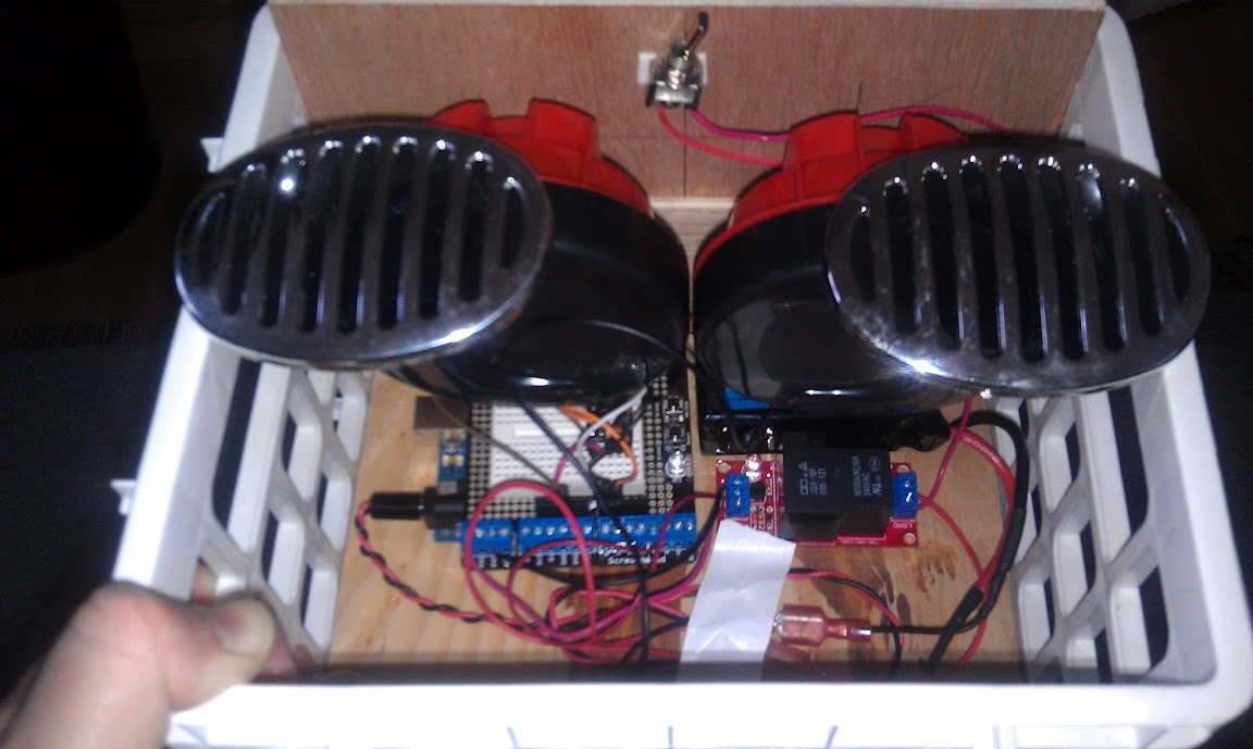
I’m putting the Auto-programmer on hold to make …. drum roll please…. The Boot Drive for Arduino!

I promised a blow by blow, and I’ve been working on this for a couple of sessions. I’ve read through all the docs (8 bit stk500 protocol, optiboot source code, AVRDUDE source.) and It looks fairly straight forward. Essentially the “programming arduino” stands in for the IDE.

The optiboot source code is pretty cleanly documented (used in most newer arduinos, like the UNO). It’s pretty tiny and does only the bare minimum to get the job done. Since it’s fairly stateless (not completely, as there are timeouts that cause you to jump to the user program), I needed to get an idea of the actual sequence.

I downloaded a trial version of AGG Software’s Advanced Serial Port Monitor which lets you “listen in” on the conversation between a computer (i.e. the Arduino IDE) and a device (the Arduino.) I collected sample program downloads for the UNO and for the Duemilanove (they have different bootloaders). There were no surprises, but it was nice to confirm the sequence. If people are interested, I could post about this later. Drop me a line on my Google+ stream.

Here’s how I have it wired (using regular Arduinos until I can get my hands on an I2SD).  Note I haven’t set up the Adafruit MicroSD breakout board yet.


I’ve got pins 2 and 3 configured as software serial on the “Master” Arduino hooked in a null modem configuration with pins 0 and 1 of the “Target” Arduino. I chose to do this, so I can send debugging info down the USB serial channel. I’m doing this at 115200, because that’s what the UNO bootloader operates at. I also hooked a digital pin from the Master to the Reset of the Target. If I read the code correctly, you have a very short period of time to start sending STK500 commands before the bootloader times out and jumps to user code after RESET. The Arduino IDE asserts reset by toggling the RTS line (well, actually a software call on the USB-serial driver). The RTS output of the FTDI chip (or equivalent on the UNO) is tied to RESET.

Now comes the frustrating part, I haven’t been able to get them to talk. I get bytes back but they aren’t what I expect, and I’m not sure where they are coming from if I’m not properly entering the bootloader.

I also tried setting up dummy programs, the Target sending “Hello” in a loop, and the “Master just trying to receive it and print it out. That doesn’t work either.

I’ll keep you posted. I’m also going to try talking to a TTL serial Arduino clone (one of the WIBLOCKS Pico boards).


Woot! Free tool!

Instructables.com is one of my favorite sites, offering step by step instructions for all kinds of projects.

Instructables author Randofo created a cool Arduino shield for programming 8 pin attinys. In a brilliant move to get more instructables submitted, he offered one for free if you submitted an Arduino or AVR instructable. Well, that pushed me over the edge and I submitted my first one:

http://www.instructables.com/id/Turn-a-TV-B-Gone-into-a-super-camera-remote/

And this is what they sent me! Cool stickers and a badge! Now I just have to come up with a Nerd sash!As an added bonus, my instructable got featured on the home page and they rewarded me with a pro membership!

Now that’s the way to develop motivation to provide content!

Since getting the shield, I’ve already hacked it. It can’t program attinys with an external clock, so I added one, and put up this instructable:

http://www.instructables.com/id/Using-the-8Pin-ATTINY-programming-shield-with-an-e/

More Noise: Sound sample

I’m a little reluctant to release this, as the police may use it on the occupy protestors. This is one annoying sound!

It was pretty hard to hear what the circuit sounded like in the video, so I modified it to have a line level output and recorded it on my computer. At first I was baffled, as the volume kept going up and down, and there were weird compression artifacts until I figured out the  sound card in my computer was doing all sorts of noise reduction and signal processing on the microphone input! I turned it off and here’s the raw sound:

Making Noise, learning electronics!

I’d seen several projects on the net to make analog synthesizers, including the classic Atari Punk Console. I’m anxious to design something of my own, but I’m still learning, so I thought I’d start small. While this is not something that hasn’t been done before, I did it entirely from scratch. I read datasheets, and experimented with values for components.

Here’s a little video overview:

I did this project iteratively, first implementing a single oscillator controlled by a variable resistor or potentiometer. The capacitor I chose (220 pF) was somewhere in the middle of the range recommended by the data sheet, though I tried several other values. I have a cheap analog scope, and I could see the oscillation, but when I tried to attach a speaker, it went dead.  I hooked up a piezo element and it could drive that, but it wasn’t very loud. I stuck in a 2N2222 transistor, and used a pot to determine the optimal (loudest) bias resistor for the base, and replaced it with a fixed value.

Next, I replaced the pot with a photoresistor. This was fun, but the tone was pretty boring (plain square wave). I then hooked up another gate to drive an LED. Pointed at the photo resistor, but some distance away, it provides a cool beat, while the “average frequency is determined by the other light hitting the photoresistor. The frequency of the beat is controlled by a potentiometer like in the first circuit.

Here’s the schematic:

One tip: You’ll notice R3 in series with the potentiometer. This is because the pot goes all the way to zero, and at zero resistance the cap won’t charge and discharge properly setting up the oscillation. This sets some non-zero base value that you can set experimentally based on what you want that end of the frequency range to be.

TI MSP430 LaunchPad First Impressions

The DangerousPrototypes Blog had a quick post on a deal that Texas Instruments was offering a Watch/development kit for their low power processors for only $24. I’ll be telling you more about this in a future installment, but while I was grabbing the deal, I saw this neat little development kit for their low-power value-line processors. It cost all of $4.30, includes two processors and all the tools you need to get going.

First, while this is an extremely cheap USB enabled development board, this is NOT an Arduino. It is however, an excellent way to introduce yourself to real “on the metal” microcontroller programming.

I downloaded all the tools, and visited their site for pointers to example code, etc.

First, TI is really trying to do the community thing, with a wiki, and featuring other people’s content.

They also have a curated portal that has links to some really cool projects too at :

http://e2e.ti.com/group/msp430launchpad/w/default.aspx

They also have a really good, structured workshop with videos and labs to really give you an overview of the platform. So far, I’m about a third of the way through the workshop, and I’m really impressed so far.

Installing Code Composer studio took a long time. It needs work on it’s installer code, as it gave all sorts of scary warnings about User Account Control in Windows 7, but in the end it worked out fine.

This eclipse based tool is TI’s flagship micro development platform and is usually licensed for a $500 or more. This
free version limits you to 16 K of code, but that’s about the biggest device in the MSP430 value line.

It’s also really nice having hardware debugging support. No more Serial printlns! Set breakpoints and examine variables. Awesome!

These processors feature super low power features. In fact the other thing I bought, the chronos watch development platform uses the same line of processors. I won’t go into all the modes here (covered very well in the workshop) but these processors know how to sip power! We’re talking microwatts or less.

The MSP430 processors feature an extremely flexible clock architecture. This allows you to do all sorts of clever things, using different clocks for different parts of the chip, or even driving external circuitry. I’m just starting to wrap my head around all this, but it’s one of the cool things my fpga friends brag about, and now I can play too!

The Von Neuman memory map (single address space for everything) is much easier to use than the atmel’s harvard architecture. No more PROGMEM weirdness. Of course you still have to be ginger about writing to flash memory (constrained to write in blocks in self programming mode the same as AVR’s).

It has pretty advanced analog to digital conversion  with DMA, so you can set it up to transfer directly to memory. Not all the chips have this but many do, and some have fancy compariters to use for pid control, etc.

All in all, I’m very impressed. I think it will be a lot of fun, and a good learning tool. It really isn’t as easy as the Arduino, so I wouldn’t recommend it for “Toe dippers” or folks looking for a quick and easy automation tool.

If they keep offering it at this price though, it could be a great teaching tool. The processors (2!) it comes with are pretty small (both in IO and memory, 2K) so it will be hard to squeeze a lot of Arduino like library in there, but for some small teaching type challenges, it may be good enough, and you can always upgrade the processor for under $3.

A week later, I also ordered the CapSense booster pack, a shield to demo the chip’s built in (no additional hardware needed) ability to handle Capacitive  touch controls. I’ll probably post more about this once I’ve had the chance to play with it.