I removed a delay in the 1.2 version of the supernikon code, so it should be more reliable now.
I also did an initial implementation of a canon remote, but I don’t have a Canon DSLR, so I haven’t tested it yet. Looks ok on the scope.
I left work a little early (around 4pm) to finish up the Cylon pumpkin. The carving went pretty well, but it was starting to get dark by the time I put the electronics in.
If you want to do this project, please don’t do as I did with scratch building, and just buy the kit. When I put the electronics in the pumpkin, they didn’t work. I pushed my fingers around on the back of the board and I could get it to work sometime.
Back upstairs, I x-acto’ed between traces where there was already corrosion (I didn’t clean the flux very well) and resoldered a few things. Whew! Got it working 1 minute before the first trick or treater came!
We’ve been so busy this season, there’s been little time for extra things. I used to go all out for Halloween, but this year we decided we couldn’t do much more than help the kids with their costumes. Well, this bothered me, and I decided to at least try to do a cool jack-o-lantern.
I’ve mentioned my love affair with EvilMadScientist.com before. They have a ton of quirky, always fun projects. (I’m still trying to convince Joyce we need an eggbot!)
They have a very nice, inexpensive kit to do a “Larson Scanner” which is a row of LED’s that scan back in forth, like in the Glenn Larson TV shows Knight Rider, and Battlestar Galactica. They also love Halloween, and published a list of their Halloween related projects. The first Cylon Pumpkin they did, was a simple slit in the pumpkin to show off the scanner, but more recently they did this awesome carving:
The project linked to this picture uses an older circuit, not the EMSL kit...
Now I haven’t carved mine yet, and I wasn’t thinking ahead. It would have been much easier to just order their kit ($13) but I had most of the parts lying around, and I stayed up late laying it out and soldering it (badly) to a proto-board. My local electronics store doesn’t have a very good selection of proto-boards, but they had a cheap (<$3) proto-board laid out like a solderless breadboard.
I’m sure this is old hat to most folks, but I realized that I could squeeze the IC in, not in the middle where it’s supposed to go, but toward one side by cutting the traces between the rows of pins for the socket.
I didn’t want wires on the front, so I tacked them from the back, and that was hard, and a little messy, as it’s very cramped especially in the middle of the attiny micro.
Once again, this whole project wouldn’t have been possible without my adafruit usbtiny ISP programmer. I used an Evil Mad Scientist minimal target board to program the chip.
EMSL’s code is a thing of beauty and a lot can be learned by studying it. Hopefully I’ll be back after tomorrow night with pictures of the finished Cylon-O-Lantern.
I’ve had a lot of fun with my TV-B-Gone, which I bought direct from Mitch Altman (the inventor) at Maker-Faire RI a couple of years ago. I particularly like turning off the plague of flatscreens at work, and every one I can see through the glass doors in my building!
I have a Nikon D90, and the little IR remote which has been very useful, but is pretty weak. It’s flakey past 5 feet, and you really have to point it right at the front of the camera. I thought, gosh, the TV-B-Gone is AWESOME, and open source, so I set about to make it into a super Nikon remote.
Here’s the 1.2 kit from Adafruit. It’s more powerful because it uses a better design of cascading transistors.
The actual hack took less than a half hour. I found someone else had done the reverse engineering of the timing on the web (http://www.alanmacek.com/nikon/)
The 1.1 software was super easy to translate the timings to. I recently bought a version 1.2 kit (the current version) and ported the software which involved mostly changing the polarity of on/off, and using a single pin instead of two.
The biggest part of this project was assembling all the bits to program. I built a usbtiny (Love it…) and used an extra TV-B-Gone pcb as a minimal target board.
The thing is Awesome! I haven’t tested how far it goes, but it hasn’t failed me yet, and it bounces around any room I’ve tried it in to be far less directional.
Thank you Mitch and Limor! Your code was great, and it was such a thrill to make something I wanted!
You can download the firmware from github. Now the only problem is switching the chips. The 1.2 version frees up a pin to use as region select, so it is possible to use it as a switch to select between camera remote and tv-b-gone.
The family and I recently drove down to Providence, RI for the Mini-Maker Faire and Waterfire. It was really mini this year, but there were some good groups there including several hacker spaces and several of my favorite micro-businesses (mostly small electronic kit makers.) I’m usually inspired by something, but often too cheap to buy the really cool stuff. I bought two LED array kits from two different vendors, thinking it would be a good learning experience, both for myself and the kids. It’s also great to support local Makers! Also, I figure I’m contributing to open source by giving them feedback. John has already responded to the feedback I’ve given him and will be updating the site, and maybe even future designs (I thought he needed bigger solder pads…)
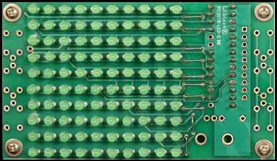
I bought two kits: a Charlieplexed 10×10 LED array from John Luciani (http://wiblocks.com) and an 8×8 LED driver based display from Modern Device. A charlieplexed display takes advantage of a quirk of microcontroller IO lines to control many LED’s with a smaller number of control lines. In the 10×10 display example, 11 IO lines are used. Since you only use the microcontroller and no additional chips, this design is much cheaper than the alternative. The disadvantage is that because it is multiplexed, the display will be dimmer and can’t really achieve full LED brightness when all the LEDs are lit. The driver version uses special LED driver chips that communicate with a serial protocol to use only 3 or 4 lines to drive many LED’s. In the Modern Device unit, it uses 4 chips (which share the same serial “bus”) each controlling 16 LEDs. Not only does this allow full brightness, the boards can be daisy chained together to make bigger displays, using the same control lines and a single microcontroller driving them.
I haven’t built the Modern Devices display yet, but I’ll share what I learned from the Wiblocks kit.
Picture from John's site. Much nicer assembly than mine.
1. John is a really nice guy!
Ok, I already knew this as I’ve met him before at various maker events, but he was really generous as well, giving me a spare PCB for one of his drawdio remix boards (I have all sorts of EVIL plans for these! Stay tuned). He accidentally gave me the wrong board (an 8×8 board), so he promptly mailed me the right one and let me keep the other.
2. Read the instructions.
Ugh, could have avoided this!
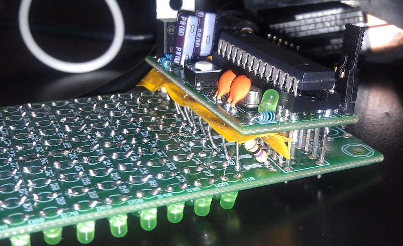
I admit I’m one of those guys who thinks winging it is better. One really cool thing about John’s designs is that he wants you to use them as a starting point, and makes them very flexible. The microcontroller board he includes with the kit is a mini version of the Arduino he calls the PICO1TR. He include instructions (and the appropriate components to build it to be compatible with 3.3V logic, or 5V logic.
Since most of my past experiments have interfaced with 5V electronics, I built the controller as 5V, and then started the LED board and found out that with 3.3V you don’t need ballast resistors (not included.) Well, not a big deal, except my stock of resistors is all 1/4 watt, and the board is quite compact and laid out for 1/8 watt resistors. This meant they stick up, and I had to add some ugly insulating material to make sure I didn’t short things out.
3. Debugging!
There were a lot of LEDs to solder, and it’s really hard to keep them all neat and straight. Fortunately I learned that flux is my friend and the soldering went very quickly, and looks pretty neat. Some of the LEDs point this way and that, but I was in a hurry. The proper way to do this is to drill holes in a piece of wood or plastic, stick the LEDs in there, and turn the board upside down and solder in place. Like I said, I was in a hurry….
I installed John’s libraries and tried to download his sample code but it wouldn’t compile. It turns out that in one of the Arduino releases since John built his library, they included an new WinAVR which has different pin names. I changed all the PB0 etc. to PORTB0 etc. I then downloaded the program to the board, and Viola it worked! Well, mostly. There was an extra LED coming on sometimes in the blank area and when that LED was supposed to be lit, it didn’t and several other LEDs lit dimly. I wrote some test code:
Turns out, the LED was in backwards, and because of the way the charlieplexed LEDs are hooked up, some current leaks into the rows and columns around it. (I haven’t completely thought this through, so that may not be entirely technically correct…) I reversed the LED and everything is cool!.
[youtube]http://youtu.be/Mp_v50feMz0[/youtube]
4. Let’s write some code!
One of the excuses I used to buy this, was that I thought it would be good to teach about arrays. Now I haven’t been brave enough to try it on a kid, I did write a bunch of bitmap manipulation routines to set and query x,y values in the array. Hmmm, what do do with that? Conway’s Life of course! I’d never written that before, but it was fun, and made me think a little! Right now I have it set to randomly re-seed after a certain number of generations, but I’ve laid the groundwork to detect static displays, and the next version will run until the current generation is just like two generations back. Another thing I wanted to learn, but is in the future, is to post code on github, and I have an account there, but haven’t gotten around to posting it yet. Until then, here is my modified library, and here is my life code. Drop the library folder in the arduino/libraries folder, and the life code is an arduino pde file (add the folder to sketchbook folder).


 Once again, this whole project wouldn’t have been possible without my adafruit usbtiny ISP programmer. I used an Evil Mad Scientist minimal target board to program the chip.
 I’ve had a lot of fun with my TV-B-Gone, which I bought direct from Mitch Altman (the inventor) at Maker-Faire RI a couple of years ago. I particularly like turning off the plague of flatscreens at work, and every one I can see through the glass doors in my building!
 The actual hack took less than a half hour. I found someone else had done the reverse engineering of the timing on the web (