Category Archives: BootDrive

Posts relating to the BootDrive project

LCDBootDrive: Selectable Files!

New toy (o-o-o)

After I showed the BootDrive on the Adafruit Show and Tell, I watched their weekly “Ask an Engineer” show where they showcased a new product, an LCD shield with an RGB backlight. The really cool thing is that the LCD AND 5 buttons only need 2 IO pins on the Arduino, because the shield is designed with an I2C expander. I ordered it the next day (close to 5pm) selected UPS ground shipping and it was at my house the next day!

Here’s a quick video before I go through the blow-by-blow:

[youtube]http://www.youtube.com/watch?v=w5jPm3thkWo[/youtube]

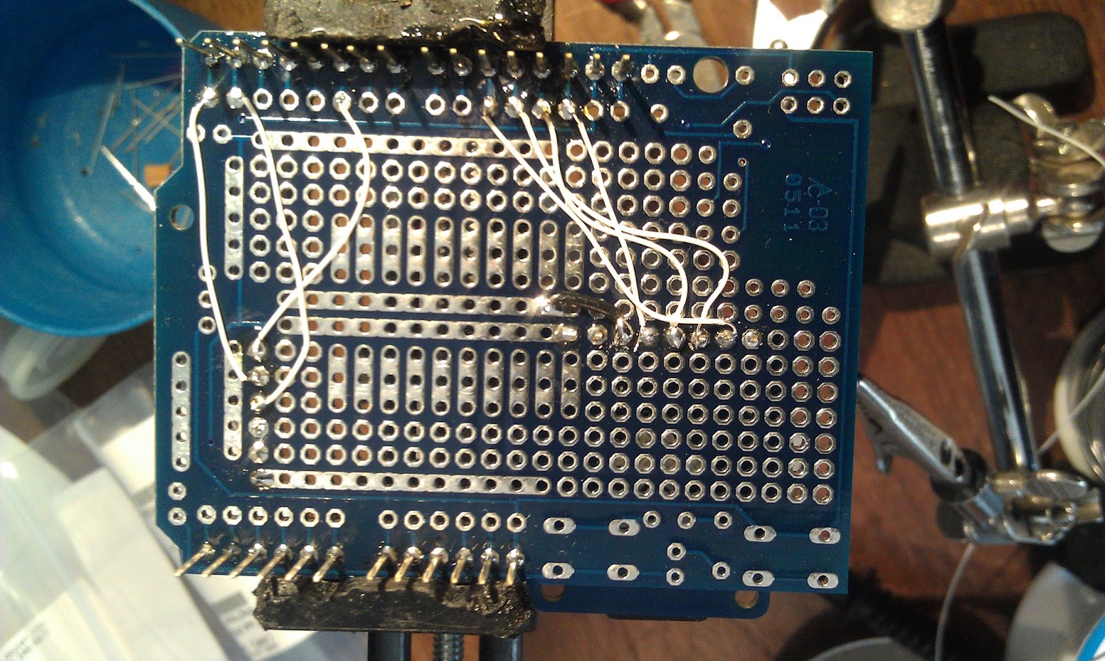
I soldered the micro-sd breakout onto an Adafruit Proto Shield, and a 6 pin right angle header to connect an FTDI cable. Adafruit also had a pre-made 6pin-6pin female cable that was perfect for this project!

I wired it with fine wire-wrap wire on the bottom

The wiring is almost identical to the original BootDrive, except I changed the reset pin assignment:

Digital Pin5  –> FTDI Pin 6 (CTS)
GND                –> FTDI Pin 1 (GND)
Digital Pin1 (RX) –>FTDI Pin 4 (TX)
Digital Pin2 (TX)–>FTDI Pin 5 (RX)

SD Card Interface:
Digital Pin 10 –> SD-breakout CS
Digital Pin 11  –>  SD breakout DI
Digital Pin 12  –> SD breakout DO
Digital Pin 13  –> SD breakout CLK
GND                    –> SD breakout GND
5V                       –> SD breakout 5V

Debugging

I incorporated the directory listing code from the SD library examples, and instead of listing all the files, I did an openNextFile() each time the “down” button was pressed. It would be nice to be able to scroll up and down, but I’m pretty tight on memory as it is, so I didn’t want to cache the directory, or do some kludgy re-reading the whole directory to get to the file we are on.

The first problem I ran into was it worked fine until you scrolled through what turned out to be 25 names (actually the same 3 names 8+ times) and then it started repeating the same name over and over. When I realized it was always 25, I knew it wasn’t some overflow, and I finally figured out the example code had a bug in it! They list the directory by opening each file (with openNextFile() to get the name, but they never close it! If you try the listfiles example with more than 25 files on the card, you’ll see only the first 25. Easy enough to fix, as I’m scrolling I close the file after I get it’s name. I reopen it if you press the “select” or program button.

The next problem was a bit harder. The hex programs seemed to work on some boards but not others, even though there were apparently no errors. I created new test programs and suddenly they didn’t work either. Since the writing to flash seemed to be working, I figured that there must be some corruption of data. I read back the programmed AVR code from the target arduino (with avrdude  <programmer parameters….> -U f:r:readfile.hex:i) and compared it with the file I was sending to be programmed. It turns out I was advancing to the next “line” of 16 bytes even when I read less. Files that ended in shorter lines were getting placed ahead of where they needed to be and so the program was corrupt. Probably on some, the data that was already there was harmless, or the program didn’t actually execute that part of it’s memory, but in some cases it clearly was. Fixed, putback to github!

Have fun and let me know if you try it!

https://github.com/osbock/Baldwisdom/tree/master/LCDBootDrive

BootDrive for Arduino

Announcing the formal release of BootDrive for Arduino. If you’ve been reading the blog, you know that I’ve been working with Justin Shaw of Wyolum labs to enable their I2SD (Arduino clone with a micro-sd card) to bootload a program onto another Arduino. After battling several issues, mostly related to porting avrdude code to the Arduino (assumptions about infinite memory, etc!) it’s working well enough people can fool around with it.

Right now the code looks for a single file (“program.hex”) and waits 5 sec and then blasts it into the target arduino. Details about setting up to try this yourself follow the video.

Here’s a demo of it in action:

[youtube]http://www.youtube.com/watch?v=i4wJ4kRO80E[/youtube]

If you’d like to try this with a couple of Arduinos, you’ll also need an SD card (or micro-sd) interface such as the Adafruit Micro-SD breakout. This board is great because it has onboard 3.3v conversion so it’s safe to use with 5V (stock) Arduinos. Download the code from github: https://github.com/osbock/Baldwisdom/tree/master/BootDrive
or a zipped version here

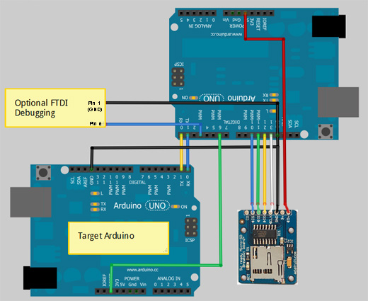
Hook up your Arduinos like this:

I

The basic setup is:

Arduino Control:
Master Digital Pin6  –> Target reset
GND                                –> GND
MASTER Digital Pin1 –>Target Digital Pin2
MASTER Digital Pin2 –>Target Digital Pin3

SD Card Interface:
 Master Digital Pin 10 –> SD-breakout CS
Master Digital Pin 11  –>  SD breakout DI
Master Digital Pin 12  –> SD breakout DO
Master Digital Pin 13  –> SD breakout CLK
Master GND                    –> SD breakout GND
Master 5V                       –> SD breakout 5V

Optional debugging serial interface (This lets you see error messages and the like)
Master GND    –> FTDI cable Pin 1 (GND)
Master Digital Pin 4 –> FTDI cable Pin 5 (diagram is wrong, but you can change it in the code if you need to)

Here are the defines you can change to swap the pins around:

#define BOOT_BAUD 115200 // This is the Arduino UNO’s bootloader baud rate. Other boards are different!
#define DEBUG_BAUD 19200 // for software serial debugging
#define txPin 4
#define rxPin 5 // not really used…
#define rstPin 6

Also if you want to put your SD card on a different line (or are using a shield that uses a different chip select) change this:

const int chipSelect = 10;

Action!

Right now, 5 seconds after initialization, the program blasts a file called “program.hex”. You can add your own user interface to select amongst multiple programs.
Just call:

void programArduino(char *filename)

with the filename, e.g.”

programArduino("program2.hex");

You can build new hex files by grabbing them from the Arduino build directory. Make sure you have the IDE set up for your target board and press the “compile/verify” button.

From http://arduino.cc/en/Hacking/BuildProcess:

The .hex file is the final output of the compilation which is then uploaded to the board. During a “Verify” the .hex file is written to /tmp (on Mac and Linux) or \Documents and Settings\<USER>\Local Settings\Temp (on Windows). During upload, it’s written to the applet sub-directory of the sketch directory (which you can open with the “Show Sketch Folder” item in the Sketch menu)

Note on Windows7, the base directory is \users\<USER> \appdata\local\Temp\build<some bunch of numbers>.tmp\<sketchname>.cpp.hex

Note that if you want to load an Arduino other than UNO, you’ll need to change the baud rate. You can find that in “hardware/arduino/boards.txt” in the arduino directory. This won’t work on MEGA based Arduinos as they use the stk500v2 protocol (thanks westfw!)

Everything You Always Wanted to know about Arduino Bootloading but Were Afraid to Ask

Breaking through!

It’s been a while since the last update, but some progress has been made. I discovered that SoftwareSerial library doesn’t work really well at 115200 baud, so I switched the wiring around to use software serial for debugging, and the hardware uart pins (Arduino pins 1 and 2) to talk to the bootloader on the target. This is a little bit of a pain, as you have to unplug the connection to the target to download code to the “programmer” but it does work now.

I had a little trouble getting sensible responses from the bootloader until I put in a delay after resetting. In retrospect this makes sense as the AVRdude code reminded me that there are capacitors on the Arduino reset line. I was probably trying to talk too soon.

What bootloader, speed, protocol?

There have been several different bootloaders in the history of Arduino, and the source code for the current “canonical” loaders is included in the Arduino software distribution.  The bootloader is a little piece of code that allows you to program the flash memory of the Arduino’s atmega328p via serial or USB instead of using an ICSP programmer.  These bootloaders implement a subset of the STK500 8bit protocol (not to be confused with STK500v2) which is documented at www.atmel.com/atmel/acrobat/doc2525.pdf

Arduino MEGA (1280 and 2560) use yet another bootloader, one that uses the stk500v2 protocol instead.

The source code for the bootloader used by the diecimila, duemilanove, and a few other clones  is in …\arduino-1.0\hardware\arduino\bootloaders\atmega. Many clones use this, or a variant hacked by Lady Ada (Limor Fried).

The UNO and other later Arduino variants use a much smaller bootloader called Optiboot (more room for your code!). A little secret is that you can actually burn this bootloader into your older arduinos (at least at atmega168 and greater) and then just refer to the board as an UNO.

Adafruit Forum user westfw (one of /the?) author of  optiboot points out:

Optiboot also supports the mega8. However, you can only call a board an Uno if it at has a m328 cpu in it. For m8 and m168s with optiboot, you’ll need to make a new entry in boards.txt that copies the Uno bootloader parameters, but has the correct “build.mcu” specification (and fuses, if you want to program the bootloader using the IDE.)

The code for this is in …\arduino-1.0\hardware\arduino\bootloaders\optiboot. If you need to change the processor or baud rate, the settings are in the Makefile. This version is very stripped down, and doesn’t support, for example, writing to EEPROM. I’m choosing to use this as my initial target. Most of the code will still work on the older bootloader, but may require a slightly different command set.

The latest and greatest optiboot can be found at it’s Google code site: http://code.google.com/p/optiboot/

Which is also the preferred place for bug reports and to check for newer versions (atmega1284 is now supported!)

Because of varying clock rates, and different bootloader code, the various boards use different baud rates to talk to the IDE. This information is found in the …\arduino-1.0\hardware\arduino\boards.txt file. The UNO programs at 115200 baud, the Duemilanove (with ATmega328p) programs at 57600 baud. The Diecemila or Duemilanove with ATmega168 programs at 19200 baud.

Looking at the actual protocol

After the Arduino IDE compiles everything down to a intel hex file for downloading to the target Arduino, it uses the avrdude command to program the Arduino. The upload protocol is also specified in the boards.txt file and is called arduino, which is a slight variant of avrdude’s stk500 protocol. Most of the commands are from the stk500 module, except the signature reading is slightly different. For now, I’m adapting the avrdude code directly for the Arduino. This requires some minor porting (eliminating fprintfs, removing some of the indirection that links it to the avrdude programmer framework). I may simplify some of this code later as I’m a little nervous about running out of room.

As I mentioned in my last post, I downloaded a trial version of AGG Software’s Advanced Serial Port Monitor, and recorded the conversation between avrdude (controlled by the Arduino IDE) and the UNO target board. I stayed up late last night annotating the conversation:

DTR and RTS are both toggled from High to low several times

Avrdude then sends the GET_SYNCH command, thows away whatever comes back and sends it again a couple of times
Avrdude/Arduino IDE:#30#20 STK_GET_SYNCH, Sync_CRC_EOP
Target/Arduino UNO:  #14#10 STK_INSYNC, STK_OK
Avrdude/Arduino IDE: #30#20 STK_GET_SYNCH, Sync_CRC_EOP
Target/Arduino UNO:  #14#10 STK_INSYNC, STK_OK
Avrdude/Arduino IDE: #30#20 STK_GET_SYNCH, Sync_CRC_EOP
Target/Arduino UNO: #14#10 STK_INSYNC, STK_OK

Get the version number of the bootloader (in this case it’s 4.4) we could use this to branch to different variants of protocol.
Avrdude/Arduino IDE: #41#81#20 STK_GET_PARAMETER, STK_SW_MAJOR, SYNC,CRC_EOP
Target/Arduino UNO: #14#04#10 STK_INSYNC, 0x04, STK_OK
Avrdude/Arduino IDE: #41#82#20 STK_GET_PARAMETER, STK_SW_MINOR, SYNC_CRC_EOP
Target/Arduino UNO: #14#04#10 STK_INSYNC, 0x04, STK_OK

The next two commands are consumed but ignored (probably used by a real programmer to retrieve device specific stuff.)
Avrdude/Arduino IDE: #42#86#00#00#01#01#01#01#03#FF#FF#FF#FF#00#80#04#00#00#00#80#00#20(This is a STK_SET_DEVICE Command that is consumed but ignored by the bootloader)
Target/Arduino UNO: #14#10 STK_INSYNC, STK_OK
Avrdude/Arduino IDE: #45#05#04#D7#C2#00#20 STK_SET_DEVICE_EXT (also ignored)
Target/Arduino UNO: #14#10 STK_INSYNC, STK_OK

Enter Programming mode.
Avrdude/Arduino IDE: #50#20 STK_ENTER_PROGMODE, SYNC_CRC_EOP
Target/Arduino UNO: #14#10 STK_INSYNC, STK_OK
Avrdude/Arduino IDE: #75#20 STK_READ_SIGN, SYNC_CRC_EOP (read device signature)
Target/Arduino UNO: #14#1E#95#0F#10 STK_INSYNC, (three byte signature), STK_OK

The next four commands are consumed but ignored. I won’t bother to reproduce them in my code.
Avrdude/Arduino IDE: #56#A0#03#FC#00#20 STK_UNIVERSAL,0xA0,0x03,0xFC,0x00 SYNC_CRC_EOP (This is a pass through command that is supposed to be used to perform arbitrary native SPI commands. In this case, and the next 3, they are Read EEPROM byte commands They are consumed but ignored by the bootloader)
Target/Arduino UNO: #14#00#10 STK_INSYNC, (last byte written by the Universal command, STK_OK
Avrdude/Arduino IDE: #56#A0#03#FD#00#20 STK_UNIVERSAL,0xA0,0x03,0xFD,0x00,SYNC_CRC_EOP (Ignored by the bootloader)
Target/Arduino UNO: #14#00#10 STK_INSYNC, (last byte written by the Universal command, STK_OK
Avrdude/Arduino IDE: #56#A0#03#FE#00#20 STK_UNIVERSAL, 0xA0,0x03,0xFE,0x00,SYNC_CRC_EOP (Ignored by the bootloader)
Target/Arduino UNO: #14#00#10 STK_INSYNC, (last byte written by the Universal command, STK_OK
Avrdude/Arduino IDE: #56#A0#03#FF#00#20 STK_UNIVERSAL, 0xA0,0x03,0xFF,0x00,SYNC_CRC_EOP (Ignored by the bootloader)
Target/Arduino UNO: #14#00#10 STK_INSYNC, (last byte written by the Universal command, STK_OK

Here’s where we actually get started. This specifies the address in Flash where the follwoing PROGRAM_PAGE data goes.
Avrdude/Arduino IDE: #55#00#00#20 STK_LOAD_ADDRESS, 0x0000, SYNC_CRC_EOP
Target/Arduino UNO: #14#10 STK_INSYNC, STK_OK
And then the actual data. Note that the data is in the same order as the bytes in the Intel Hex file
Avrdude/Arduino IDE:
#64#00#80#46#0C#94#61#00#0C#94#7E#00#0C#94#7E#00#0C#94#7E#00#0C
#94#7E#00#0C#94#7E#00#0C
#94#7E#00#0C#94#7E#00#0C#94#7E#00#0C#94
#7E#00#0C#94#7E#00#0C#94#7E#00#0C#94#7E#00#0C#94#7E#00#0C#94#7E
#00#0C#94#7E#00#0C#94#9A#00#0C#94#7E#00#0C#94#7E#00#0C#94#7E#00
#0C#94#7E#00#0C#94#7E#00#0C#94#7E#00#0C#94#7E#00#0C#94#7E#00#0C
#94#7E#00#00#00#00#00#24#00#27#00#2A#00#00#00#00#00#25#00#28#00#2B
#00#00#00#00#00#20
STK_PROGRAM_PAGE, 0x0080 (page size), ‘F'(flash memory), data bytes…,SYNC_CRC_EOP
Target/Arduino UNO: #14#10 STK_INSYNC, STK_OK

And then we repeat – set address, program page, etc.
Avrdude/Arduino IDE: #55#40#00#20 STK_LOAD_ADDRESS, 0x0040, SYNC_CRC_EOP
Target/Arduino UNO: #14#10 STK_INSYNC, STK_OK
A
vrdude/Arduino IDE: STK_PROGRAM_PAGE, 0x0080 (page size), ‘F'(flash memory), data bytes….,SYNC_CRC_EOP
Target/Arduino UNO: #14#10 STK_INSYNC, STK_OK
.
.
.
Then it reads several pages (probably to verify what it wrote)

Avrdude/Arduino IDE: #55#00#00#20 STK_LOAD_ADDRESS, 0x0000,SYNC_CRC_EOP
Target/Arduino UNO: #14#10 STK_INSYNC, STK_OK 

Avrdude/Arduino IDE: #74#00#80#46#20 STK_READ_PAGE,0x0080 bytes, ‘F’ for flash, SYNC_CRC_EOP
 Target/Arduino UNO #14 STK_INSYNC
Target/Arduino UNO #14#10 STK_INSYNC, STK_OK
#0C#94#61#00#0C#94#7E#00#0C#94#7E#00#0C#94#7E#00#0C#94#7E#00#0C#94#7E
#00#0C#94#7E#00#0C#94#7E#00#0C#94#7E#00#0C#94#7E#00#0C#94#7E#00#0C#94
#7E#00#0C#94#7E#00#0C#94#7E#00#0C#94#7E#00#0C#94#7E#00#0C#94#9A#00#0C
#94#7E#00#0C#94#7E#00#0C#94#7E#00#0C#94#7E#00#0C#94#7E#00#0C#94#7E#00
#0C#94#7E#00#0C#94#7E#00#0C#94#7E#00#00#00#00#00#24#00#27#00#2A#00#00
#00#00#00#25#00#28#00#2B#00#00#00#00#00 

#10 STK_OK

repeat several times at different addresses

.
.

And then leaves programming mode
Avrdude/Arduino IDE: #51#20 STK_LEAVE_PROGMODE, SYNC_CRC_EOP
Target/Arduino UNO #14#10 STK_INSYNC, STK_OK

Then we’re done! Avrdude then toggles DTR/RTS to reset


Detour: From Auto-programmer to Serial Boot drive

When I originally posted about the Auto-programmer I was pleased to see several people on my Google+ stream and in the Adafruit forums were interested. Justin Shaw of Wyolum labs was interested in the idea of reading the program off the SD card, but instead of programming a microcontroller chip directly, program another Arduino compatible (specifically one of his gorgeous clocks!)

He’s already made an Arduino compatible SD card reader board he calls I2SD (it speaks I2C) that also speaks TTL serial, so it would be perfect. I’m putting the Auto-programmer on hold to make …. drum roll please…. The Boot Drive for Arduino!
I promised a blow by blow, and I’ve been working on this for a couple of sessions. I’ve read through all the docs (8 bit stk500 protocol, optiboot source code, AVRDUDE source.) and It looks fairly straight forward. Essentially the “programming arduino” stands in for the IDE.

The optiboot source code is pretty cleanly documented (used in most newer arduinos, like the UNO). It’s pretty tiny and does only the bare minimum to get the job done. Since it’s fairly stateless (not completely, as there are timeouts that cause you to jump to the user program), I needed to get an idea of the actual sequence.

I downloaded a trial version of AGG Software’s Advanced Serial Port Monitor which lets you “listen in” on the conversation between a computer (i.e. the Arduino IDE) and a device (the Arduino.) I collected sample program downloads for the UNO and for the Duemilanove (they have different bootloaders). There were no surprises, but it was nice to confirm the sequence. If people are interested, I could post about this later. Drop me a line on my Google+ stream.

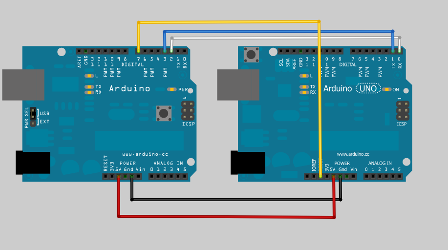
Here’s how I have it wired (using regular Arduinos until I can get my hands on an I2SD).  Note I haven’t set up the Adafruit MicroSD breakout board yet.


I’ve got pins 2 and 3 configured as software serial on the “Master” Arduino hooked in a null modem configuration with pins 0 and 1 of the “Target” Arduino. I chose to do this, so I can send debugging info down the USB serial channel. I’m doing this at 115200, because that’s what the UNO bootloader operates at. I also hooked a digital pin from the Master to the Reset of the Target. If I read the code correctly, you have a very short period of time to start sending STK500 commands before the bootloader times out and jumps to user code after RESET. The Arduino IDE asserts reset by toggling the RTS line (well, actually a software call on the USB-serial driver). The RTS output of the FTDI chip (or equivalent on the UNO) is tied to RESET.

Now comes the frustrating part, I haven’t been able to get them to talk. I get bytes back but they aren’t what I expect, and I’m not sure where they are coming from if I’m not properly entering the bootloader.

I also tried setting up dummy programs, the Target sending “Hello” in a loop, and the “Master just trying to receive it and print it out. That doesn’t work either.

I’ll keep you posted. I’m also going to try talking to a TTL serial Arduino clone (one of the WIBLOCKS Pico boards).