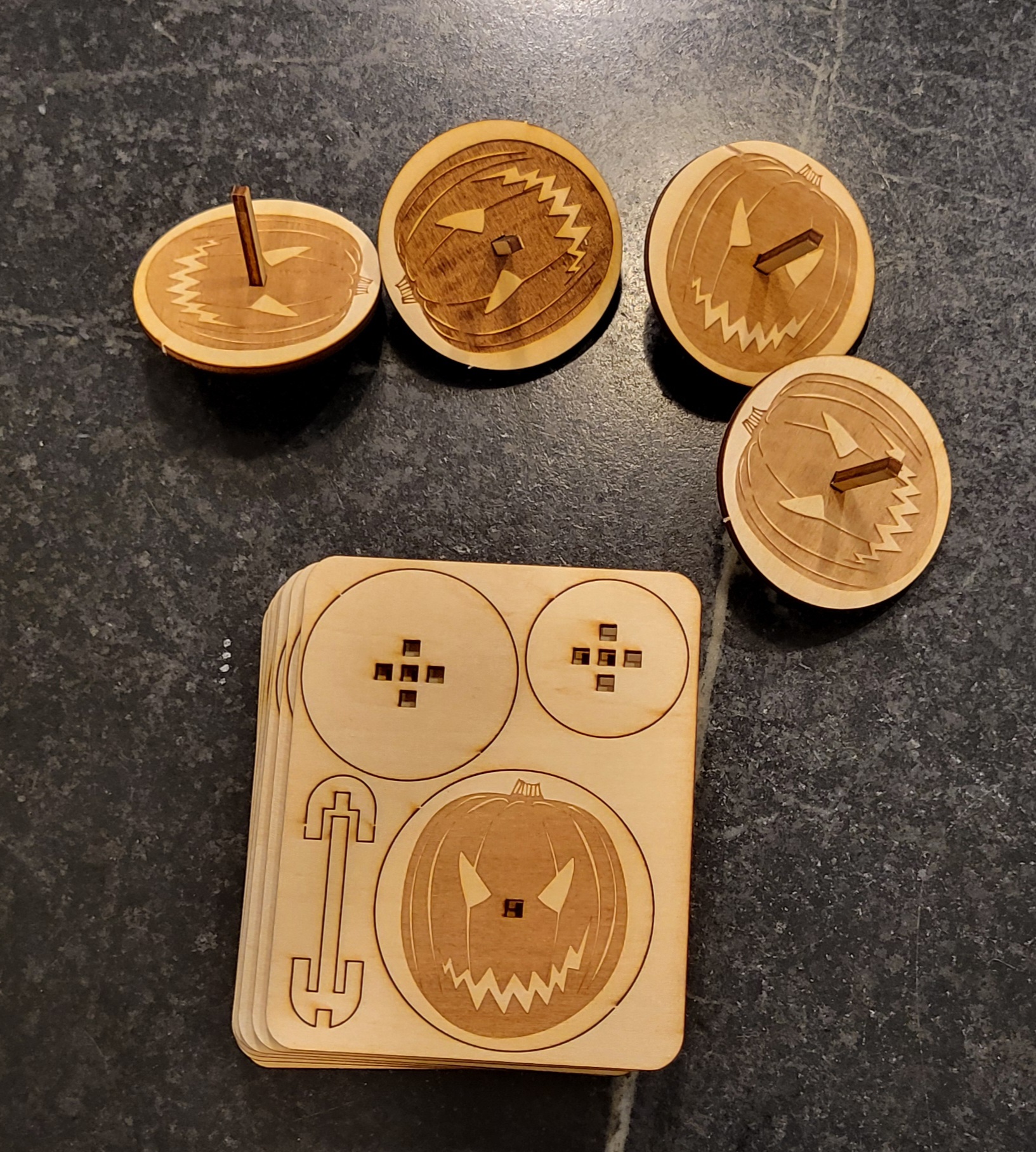
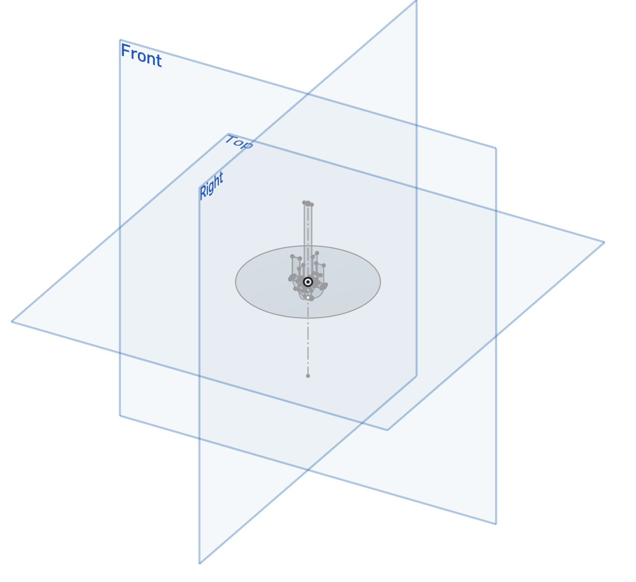
My friend runs a cool open crafting studio, Knot and Purl and I wanted to help her with some give-aways for her Halloween open house. I’ve always wanted better cad for laser crafting, so it was a good opportunity to experiment with different CAD methods. I first modeled it in Onshape. Exporting each of the sketches was a little tedious, but the tools were pretty nice, and it was easy to make the design parametric.
FreeCad is something that has been getting better, and I could learn how to do assemblies to make better pictures for assembly instructions.
The sources and some SVG’s are saved here.
The Sketches were fairly easy (though you really do have to think about how the holes and tabs enlarge and shrink due to the laser’s no-zero kerf.
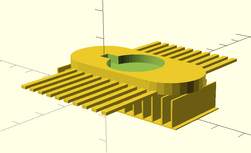
It was easy to extrude the sketches to make the full top.
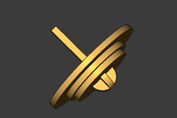
I added sliding joints to an assembly. I think the limits can be improved in a parametric fashion, but I was able to make a cool animation.
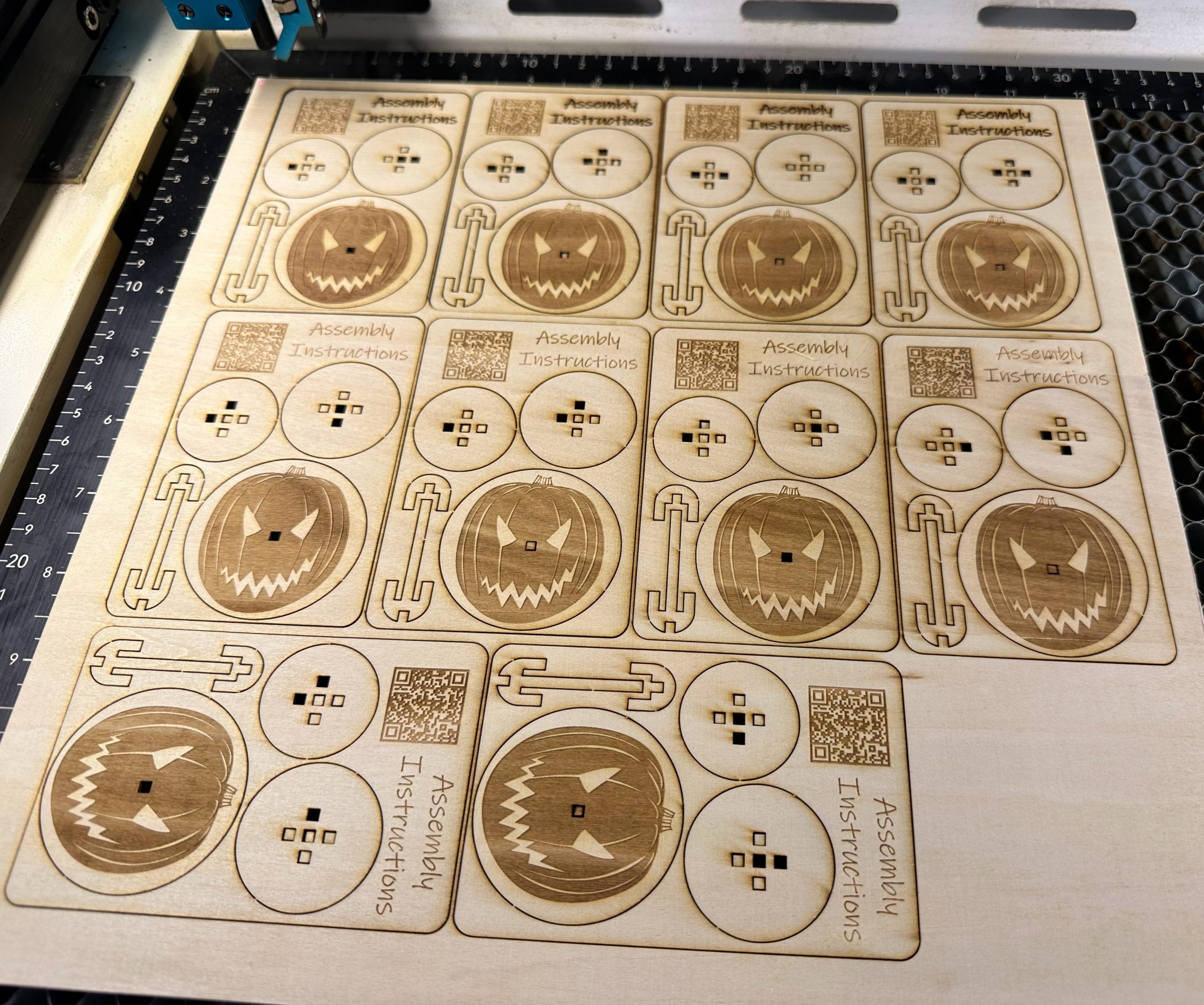
The TechDraw workbench also allowed me to export all the parts in one sheet:
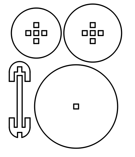
The SVG export was somewhat doubled. The full figures were on a lower layer, and individual paths were duplicated on top of that. The DXF export however was perfect.
I then wanted to make a kit, and initially I edited the paths in lightburn to make little gaps in each of the outlines to make “tabs.” This is great for a file to share, but it was also easier to use the generate tabs feature in lightburn.
The last thing was to add a QR Code linking to the assembly video.

 This works out quite nicely, and gives a speedier print.