Category Archives: electronics

Open Hardware Summit Photobooth

As you know, my Wyolum buddies and I partnered up with SeeedStudios to make a really cool e-paper badge for the Open Hardware Summit which took place last week. We wanted some cool ways for people to customize their badges. Justin created a great simple program for converting images (wifit.py) and I leveraged that software to create a photobooth.

photobooth (by Addie Wagenknecht)
Photo by Addie Wagenknect

My friend Michael Castor at Makershed built a cool tablet from the Raspberry Pi, and he told me about the nice 10.1″ LCD display and HDMI adapter he found from Chalk-elec.

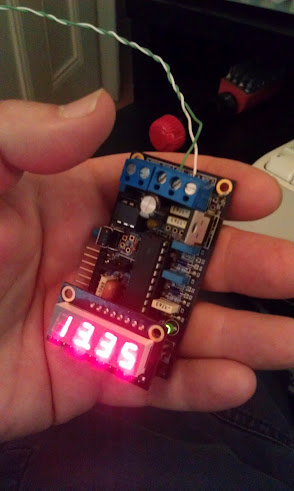
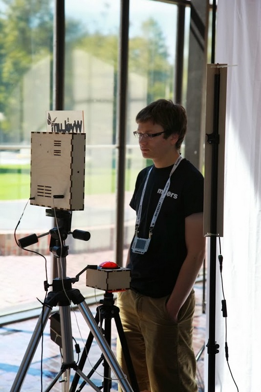
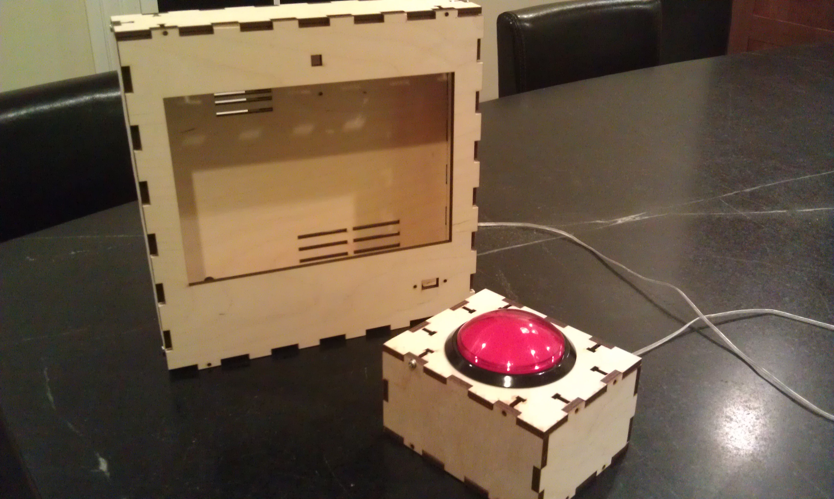
I ordered one, and started figuring out how to put the whole thing together. I also got a big red button from Adafruit. I have been playing with the Raspberry Pi camera and it’s perfect for embedding in a project like this, even though the software is a bit primative at this point (no video for linux drivers, etc.) I used our own AlaMode to read the button and use one of our WS2811 arrays to do a visual countdown before taking the picture.

I’d never really designed anything for laser cutting, and this was my opportunity! I used Inkscape, with the T-slot extension written by Justin. I got the box cut at Einstein’s Workshop (a family oriented makerspace in Burlington, MA.)

Lasercut box

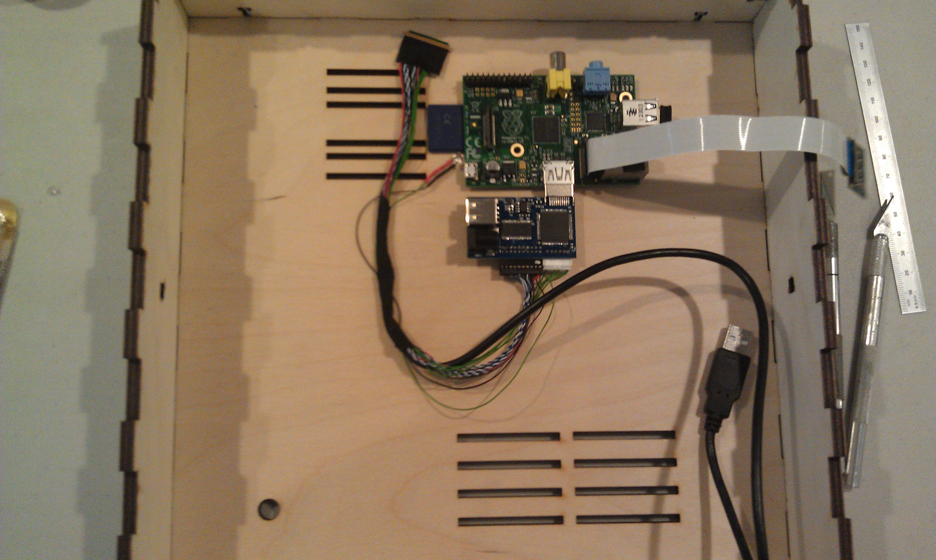
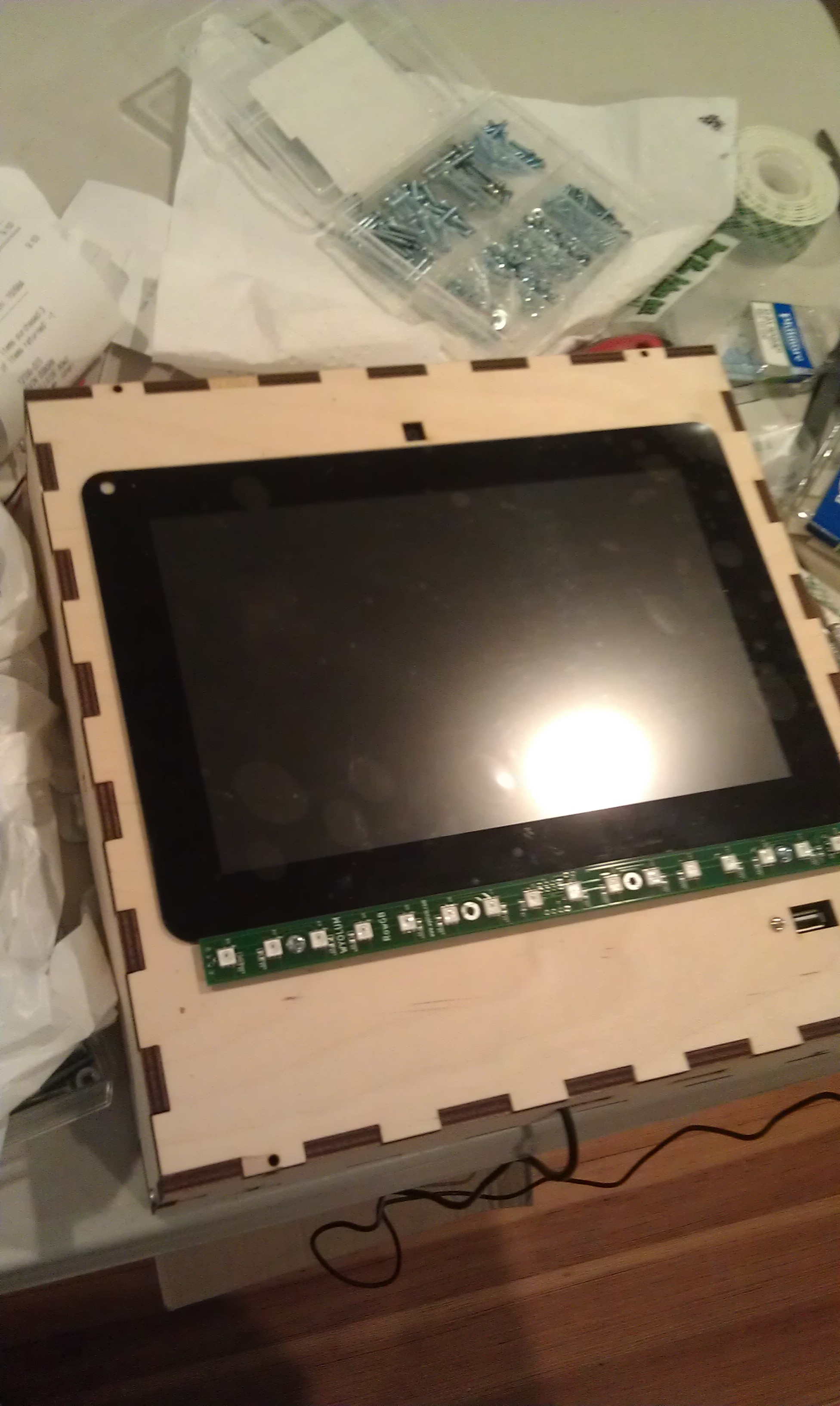
Next, I laid out the components. The trickiest parts were the LVDS cable (though it’s pretty generous) and the Raspberry Pi Camera flex cable.

One really sweet thing about the Chalk-elec hdmi adapter is that you power it, and there’s a USB power port to power the Pi.

Raspberry Pi and HDMI adapter


Attaching the LCD to the case is a little nerve wracking, as like most tablet screens, it’s intended to be glued in. I used 3M permanent mounting tape (really not tape but adhesive on a backing roll.) It’s really difficult to cut with scissors (it sticks to everything) I made the mistake of putting it on the bezel and trying to cut it with an X-acto knife. I scratched the paint on the bezel, but I managed to fix it with a sharpie.

The better approach turned out to attach it to the opening, and cut along the opening.

IMAG1720-001

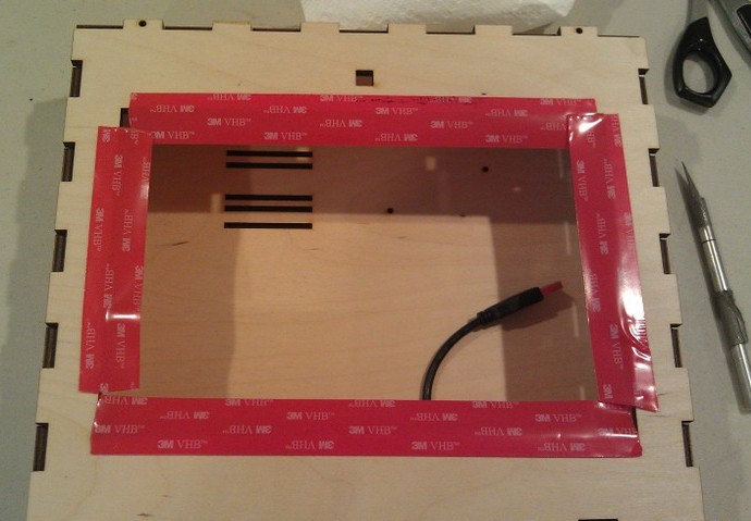
After trimming I added the LCD, and the USB panel mount jack.

I had to drill a few holes because I hadn’t completely planned ahead, for a jack for the switch box (used a 1/4 phone jack and plug) power, and the 16 pixel LED array.

IMAG1726


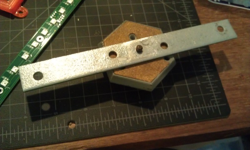
I had planned for it to swivel on the sides from two carriage bolts with wing nuts. This meant making a stand, and I didn’t want it to be just a couple of 2×4’s. Also I was running out of time so I took Justin’s suggestion and made a tripod mount for it. More holes…. And a mending plate from the hardware store. Fortunately I have a set of cheap taps from Harbor Freight, so it was pretty simple to drill the plate and tap it (1/4-20) to accept a tripod mount.

IMAG1730

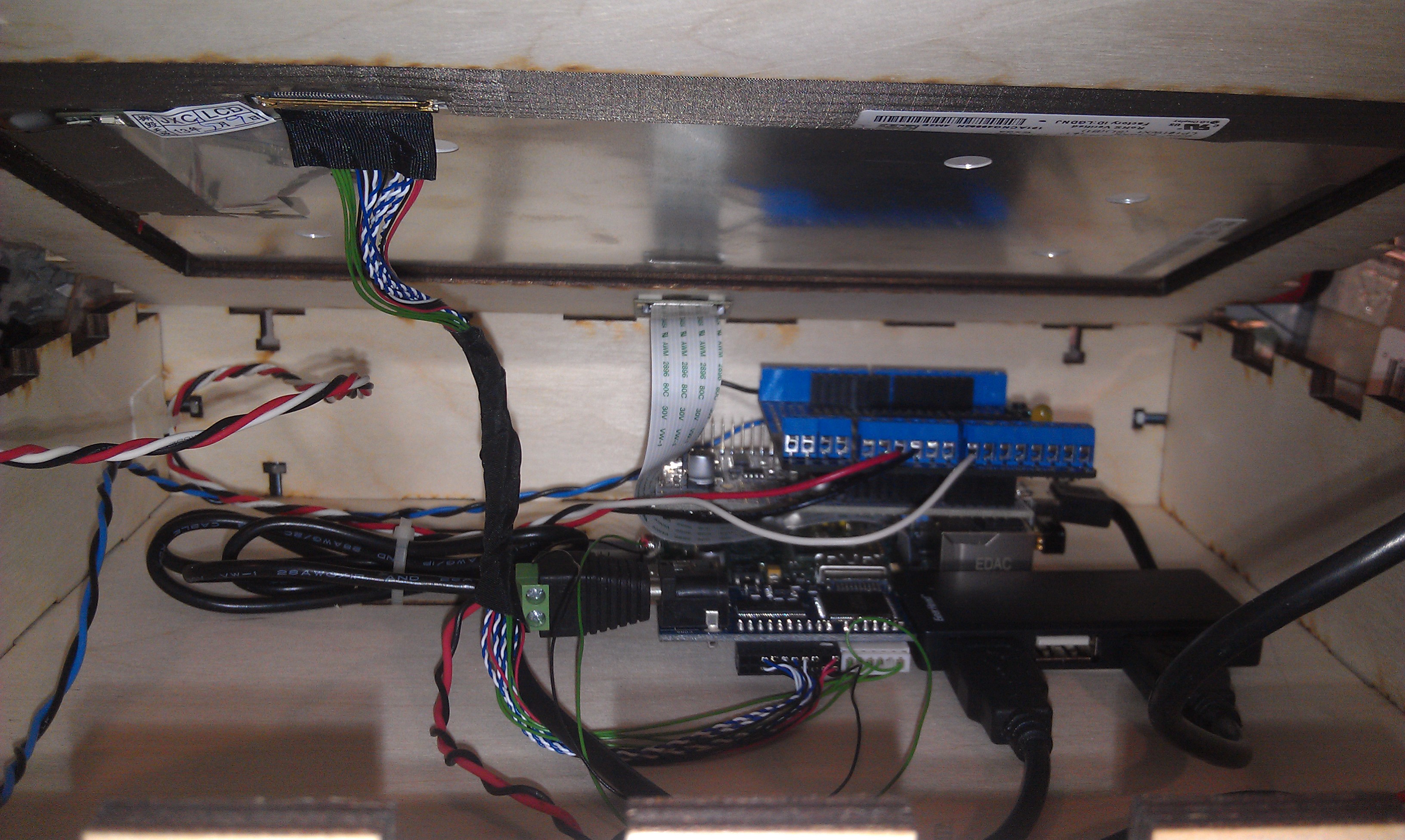
Getting it hooked up with the short cables is a little tricky, but there’s room to get your hands in there:

IMAG1732I

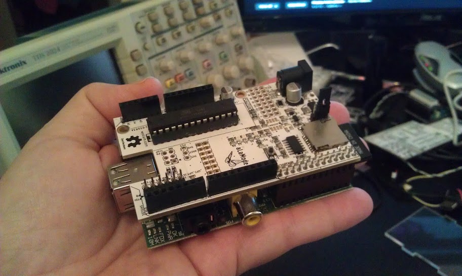
I used a proto-screw shield to make it easier to hook up the button and LED leads. As you can also see, there’s a small usb hub inside too.
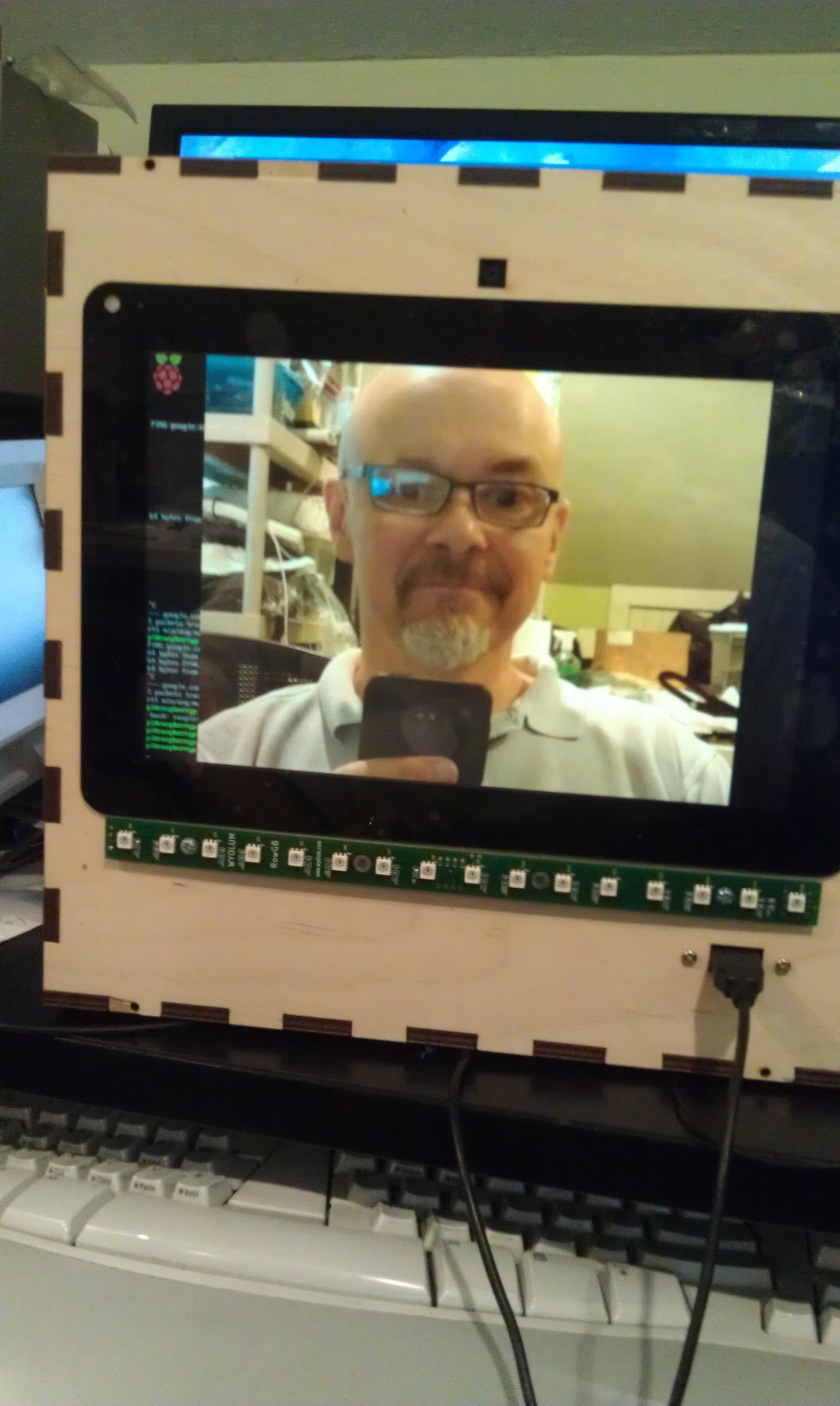
I booted it up:

IMAG1727


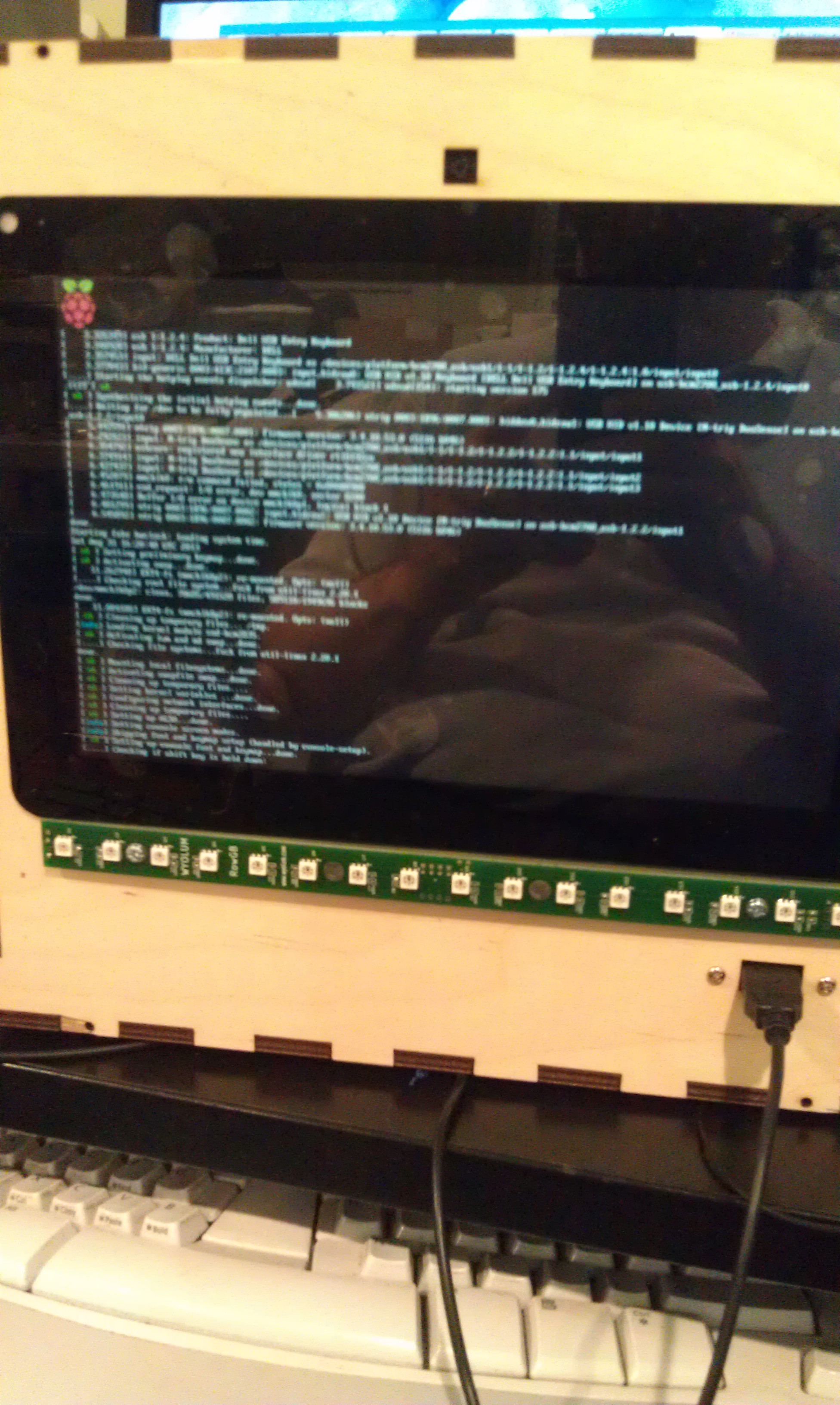
and then hacked Justin’s Wifit program to take a picture:

IMAG1728

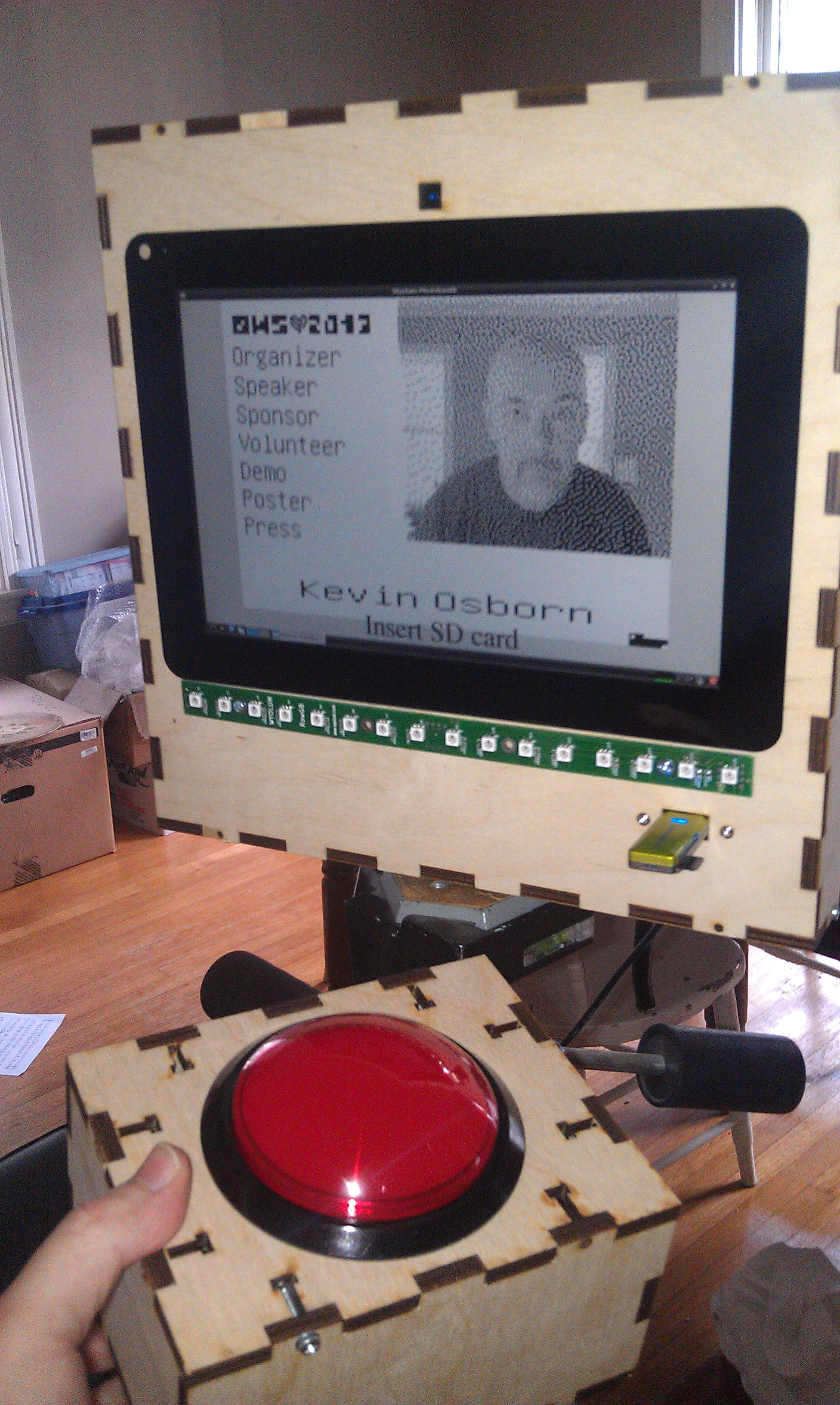
Justin then created a more kiosk-y gui, and I ironed out a few things with the Arduino code for AlaMode. The gui checks to see if an sd card is mounted, and when it is, it sends an enable command to the button and prints on the screen “Press Button when ready”  The AlaMode then monitors for the button, and when pressed, sends the signal to take the picture and begins counting down on the LED strip. You can find the code in our github repository: https://github.com/wyolum/EPD

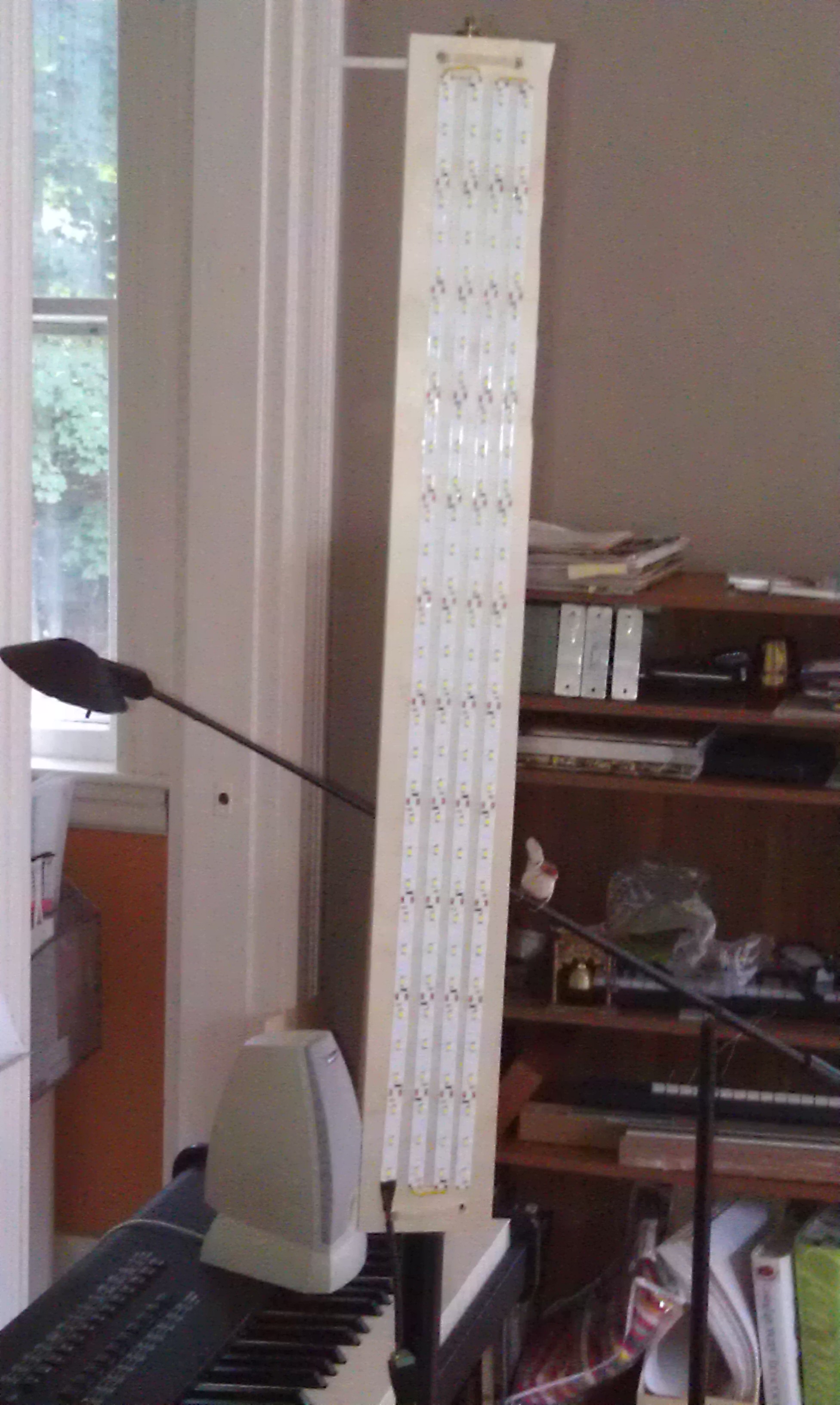
I tried also using the LED strip as a flash, and it worked but made sort of ghastly underlighting like a camp flashlight! So I took some cheap chinese led strip I had around (about $12 for 5 meters) and made a light panel:

IMAG1753

And the finished product:
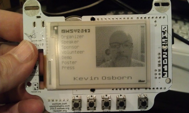
IMAG1745

And on the badge:

IMAG1729I’m thinking of modifying the code to upload higher res pics to the Internet with an imprint, or printing them on a portable printer I picked up at a yard sale!

By the way, I left the Raspberry Pi’s wifi dongle attached, as it made it much easier to debug with SSH from my laptop. That said, I did also plug another hub into the one exposed port to use a keyboard and mouse (even though the touch screen does work!) If I had to do it over again, I might bring at least one more port out for other devices.

You’ll notice in the first picture, the Wyolum Logo across the top. Elizabeth Shaw cut that for me and delivered it the morning of the OHS, and it fit perfectly!


Lazertag hacking

My friend Nick asked if we could find a way to create enhancements to the fantastic, but no longer made Lazertag Team Ops system.

Many people believe that this was the Pinnacle of consumer lazertag, and I tend to agree. In addition to working better both indoors and out, it could host games where it kept track of the scores of multiple players.

Nick and his friend Max came over and we were totally successful! Here’s a brief video showing our results.

[youtube]http://youtu.be/x3LsPc1kz2I[/youtube]

First we looked up what was known about the protocol. I found this:

http://web.archive.org/web/20090304155723/http://lasertagparts.com/ltto.htm

via the LTTO (LazerTagTeamOps) Yahoo group. As you can see the page is no longer in service, but the archive still has it.

Here’s the cool diagram that they created in the past, apparently based on Aaron Nabil’s reverse engineering effort:

From the Internet Archive’s record of http://www.lasertagparts.com/images/ltto_signals.gif

Of course it’s easy to say this now, but the protocol was pretty easy to decode by looking at the output on a scope. The only difficulty I had was capturing just the shot, as the dome is constantly shooting out messages saying what team, etc.

Here’s an example of a shot that is created by our program:

Lazertag shot

you can see that it uses a 38 kHz carrier (to distinguish it from random IR noise. Fortunately Ken Shirriff wrote a terrific IR Remote library for the Arduino. It’s not really well documented, but there is a sendRaw() function that we used to send the actual timings for the shot. Grab his library here. The library uses preset pin numbers for the LED output, but you can change them in the library itself, you just need to use one of the PWM pins as he uses the timer function to create the carrier frequency.

[code]

unsigned int shootOne[] = {3000,6000,3000,2000,1000,2000,1000,2000,1000,2000,1000,2000,1000,2000,1000,2000,1000};

// the one confusing thing with the irsend.sendRaw command is that the last argument is labled hz, but it’s really
// kiloherz. The lazertag team ops uses the common 38kHz frequency.
irsend.sendRaw(shootOne,sizeof(shootOne)/sizeof(int),38);

[/code]

For the TV-B-Gone, I modified the original firmware to send out the appropriate pulses, similar to my previous hack for camera remotes. The V1 firmware uses uncompressed codes, so that is what I started with.

Grab the example code zip here, and let me know on google+ if you build anything with it!

Also if you want to use Git to pull the code (whether or not you want to fork) it’s all checked in to the baldwisdom github repo:

https://github.com/osbock/Baldwisdom


Introducing Raspbery Pi à la mode

Our first prototypes are back, and working quite well! SeeedStudio fabricated the prototype boards and quickly sourced the parts.  The boards were of excellent quality. We ran into a few hiccups along they way, but Seeed Studio took care of them right away, and rushed to make up time.

If you haven’t been following, Anool Mahidharia, Justin Shaw and I from the Wyolum.com OSHW collaborative have been developing a stackable Arduino compatible for the Raspberry Pi.

While there are lots of emerging examples of interfacing hardware to the Pi, it’s just not as easy as the Arduino, and the Arduino already has hundreds of libraries for interfacing with motors, sensors, and displays. While you can always plug an Arduino into the USB port, but it’s not as neat and embed-able as a a GPIO interfaced board. You can write a program on the Pi in any language you want to control or monitor your Arduino application, making Internet integration and control super easy. In addition you can even program the AlaMode directly from the Pi.

Here are the features including a few extra goodies:

  • Flexible power. Can be powered directly from the Pi, standalone with a battery or wall-wart, or USB power. This is important if your shield takes more power than the Pi can provide or if you want to undock it for standalone operation.
  • Programmable via the Pi’s UART on the GPIO pins, or an FTDI USB-Serial adapter or ISP.
  • Header for connecting Fastrax UP501 GPS.
  • DS3234 Real time Clock. The Pi doesn’t have it’s own battery backed RTC. You can set a program in the AlaMode to report the time to the Pi via serial or I2C
  • Micro-SD card slot. Useful for datalogging, and big-memory  for your Arduino applications
  • Row of Servo Headers connected to the PWM pins with a configurable power and ground rail

We’re in limited Beta right now, but as soon as it’s thoroughly tested, we hope to produce them for sale as soon as we can!

Introducing: Carduino, a micro for Car hacking.

Becoming a member of Wyolum has it’s privileges (and responsibilities)! While waiting for my AlaMode boards to come back, I’ve been helping out on another project led by David Pincus, with electronics and layout by Anool Mahidharia.

David originally wanted this to supply power to his new in-car DVR that has the capability of recording triggered by motion detected by it’s on-board accelerometers. He was worried that if he didn’t drive the car for a few days, it might drain the battery. This little Arduino compatible board can monitor two voltages (through a precision resister voltage divider) and shut off a solid state relay if the voltage falls below a selectable value. There’s also an optional display board (shown here displaying the supply voltage). If you don’t want to use the display, the row of pins is a handy breakout of many of the unused Arduino pins.


Other features:

  • i2C port (sensors anyone?)
  •  2.5 A solid state relay.
  • Jumper block for setting shutdown voltage. Here we got a bit clever, using a resistor ladder tied to an analog pin. Uses just one pin but multiple values.
  • FTDI and ISP programmable
  • Can be powered by FTDI or VBATT input (up to 15V)
  • Protection diodes on all the power inputs
  • Screw terminals for easy connection.
  • Easy to assemble through hole kit.

We’re making a few tweaks, and then we are thinking about doing a kickstarter to judge interest. We’d love to hear what you’d do with it, I think the applications aren’t limited to cars. Certainly, boats, RV’s and maybe solar applications also come to mind.

I’ve learned a lot on this project. I did the logistics, ordering the boards from Laen (http://oshpark.com, Dorkbot PDX’s new online submission system), kitting parts and writing some test code and trying out the first version.

If you are interested, give us a shout (either on my google+ stream, or at the wyolum.com forums.)

Raspbery Pi à la mode ?

Lot’s of people are excited about the Raspberry Pi®, a complete computer for $25 (or $35 with ethernet).
The initial shipment is entirely sold out, and there are 200,000 more on order. Lots of people have been saying that this is the end of the Arduino, as it’s about the same cost, a full linux system with keyboard, mouse, and hdmi video output.

I think this is an oversimplification. Arduino is fantastic at interfacing to the physical world in a way that no linux (or Windows) PC could hope to approach at any cost.

The Pi does have a GPIO connector, but it pales in comparison to the humble Arduino. No built in PWM (servos anyone?) and no Analog to digital conversion.

Why throw the baby out with the bathwater? How about some delicious ice cream with your Raspberry Pi?
As a member of the amazing Open Source Hardare collective Wyolum.com,  I’m working with Justin Shaw and  Anool Mahidharia on “à la mode”: an Arduino clone specifically for the Raspberry Pi (That rendering above is courtesy of our  fabulous  EE  Anool) . You can of course connect an Arduino to a Pi USB port, but when you want a turnkey solution, how about an Arduino compatible “plate” (what the Pi folks call shields) that fits right on top of the Raspberry Pi.

You can plug your existing shields right in,  and you can even run the Arduino IDE on the Pi. Since the Pi’s core mission is to provide equal access to computing to all children, this will also give the kids the opportunity to mix it up “Arduino-style” with real world hardware.

We couldn’t have a vanilla add-on, so we added:

  • A battery backed real time clock: RTC: DS3231 (same as ChronoDot)
  • uSD card for logging
  • Socketed Atmel Atmega 328p in case you make a wiring mistake and need to replace it.

We’re sending off for prototype boards soon, so if you have feedback, let us know! Join the conversation at the Wyolum.com forums.

Raspberry Pi® is a trademark of the Raspberry Pi Foundation.

Arduino Library for Scratch Sensor Board Emulation

I re-wrote the simple sketch as an Arduino Library for Scratch Sensor Board (picoboard) emulation.

You can download it at github

Unzip the contents of this repository into a directory called ScratchSensors in the Arduino libraries directory (or in Sketchbook/libraries)

In your sketch: #include <ScratchSensors.h>

and then: ScratchSensors Scratchboard;

In Setup: Scratchboard.init();

Sensor values are stored in an array internally to the ScratchSensors class called Values[];
The picoboard/Scratch sensor board that is emulated has specific sensor labels that are reported:
#define RESISTA 0
#define RESISTB 1
#define RESISTC 2
#define RESISTD 3
#define SLIDER 4
#define LIGHT 5
#define SOUND 6
#define BUTTON 7

Values should be between 0 and 1023. These are scaled by scratch to be between 0 and 100. BUTTON is handled in a special way: 0 is depressed and 1023 is not pressed. Let’s say you have an analog sensor like an accelerometer connected to Arduino pins A0, A1, and A2. Then during loop():

Scratchboard.Values[RESISTA] = analogRead(A0);
Scratchboard.Values[RESISTB] = analogRead(A1);
Scratchboard.Values[RESISTC] = analogRead(A2);

then, write the packets out to the serial/usb port: Scratchboard.report();

There’s an example in the examples directory based on the Sparkfun midi shield. It has two pots and three buttons. Of course only one of the buttons can be used with the Scratch buttonpressed semantics, but the others can be tested for specific values.

Interfacing Scratch to the Arduino Platform

I’m a big fan of Scratch, the educational programming language created at MIT. International Scratch Day is coming up, and when we went two years ago, we had a blast. Last time, I added a distance sensor to an Arduino, made it emulate a Scratch Sensor Board, and  put it under a trampolene. This year, I decided to document the general process of making your own scratch sensors and bring a compact sensor module for the kids to play with.

At one point during our research at work, we needed a way to measure the movement and relative distance of a camera platform, so I designed, and my tech put together a combination of a Teensy (Arduino Compatible microcontroller), an Adafruit ADXL335 Accelerometer breakout, and a Sharp IR distance sensor.

I dug up my old code for the trampolene hack, which was based on some code I got off the Scratch forums. It didn’t work!

What we are actually doing is emulating what was originally called a “Scratchboard” and now produced by a company called the Playful invention company and called a “PicoBoard”.

There’s a spec (and schematics) at http://info.scratch.mit.edu/sites/infoscratch.media.mit.edu/files/file/ScratchBoard_Tech_InfoR2.pdf

Turns out, the platform used to be more forgiving, and now it expects a report of all the sensors (whether we are using them or not.)

The IR distance Sensor outputs an analog voltage proportional to the distance to the nearest thing in it’s path, and likewise the accelerometer outputs a voltage proportional to the acceleration (including gravity). I mapped the distance sensor to the “slider” sensor, and the X, Y and Z outputs to the Resistance A, B and C sensors.

Here’s a demo video:

[youtube]http://www.youtube.com/watch?v=wVa8QUz5DxI[/youtube]

I’m planning on re-working the interface code into an Arduino Library, and I’ll post that here when I get it done.

In the meantime here’s the Arduino code:

// Scratchboard emulation
// by Kevin Osborn
// http://baldwisdom.com
// Feel free to use this code in any way you wish! (Though if you want to link
// to my blog, that would be cool)
// The Scratchmote has a sharp ir distance sensor
// and a 3 axis accellerometer

#define DISTSENSE A0
#define ACCELX    A1
#define ACCELY    A2
#define ACCELZ    A3

#define TESTMODE  0

// Format output for ScratchBoard emulation
// sensor=0-7, value=0-1023 (rescaled by Scratch to 0-100)
// 0="A", 1="B", 2="C", 3="D",
// 4="Slider", 5="Light", 6="Sound", 7="Button"
void ScratchBoardSensorReport(int sensor, int value)
{
  Serial.write( B10000000
                 | ((sensor & B1111)<>7) & B111));
  delayMicroseconds(400);
  Serial.write( value & B1111111);
}
int flatx,flaty,flatz; // might be used to set midpoint
int maxX,minX; //testing purposes
int lastx,lasty,lastz;

void setup()
{
  pinMode(DISTSENSE, INPUT);
  pinMode(ACCELX,INPUT);
  pinMode(ACCELY,INPUT);
  pinMode(ACCELZ,INPUT);

  lastx =maxX= minX = flatx=analogRead(ACCELX);
  lasty = flaty=analogRead(ACCELY);
  lastz = flatz=analogRead(ACCELZ);

  Serial.begin(38400);
}

void loop()
{
  int distance = abs(map(analogRead(DISTSENSE),0,650,0,1023)-1023);
  //experimenting with the ADXL335 gives us readings between low single digits
  // and < 700 for human powered movements   int x = map(analogRead(ACCELX),0,700,0,1023);   int y = map(analogRead(ACCELY),0,700,0,1023);   int z = map(analogRead(ACCELZ),0,700,0,1023);      int rx = (x +lastx)/2;   int ry = (y +lasty)/2;   int rz = (z +lastz)/2;      lastx = rx;   lasty = ry;   lastz = rz; #if TESTMODE Serial.println(distance); /* Serial.print("x,y,z= "); Serial.print(x);Serial.print(","); Serial.print(y);Serial.print(","); Serial.println(z); */ if (x > maxX) maxX=x;
if (x< minX) minX=x;
Serial.print("maxX = ");Serial.println(maxX);
Serial.print("minX = ");Serial.println(minX);
delay(500);

#else
if (Serial.available())
{
  if (Serial.read() == 0x01){
  ScratchBoardSensorReport(0,rx);
  ScratchBoardSensorReport(1,ry);
  ScratchBoardSensorReport(2,rz);
  ScratchBoardSensorReport(3,0);
  ScratchBoardSensorReport(4,distance);  
  ScratchBoardSensorReport(5,0);
  ScratchBoardSensorReport(6,0);
  ScratchBoardSensorReport(7,0);
  }
 //ScratchBoardSensorReport(1,analogRead(POT2));
 // ScratchBoardSensorReport(7,digitalRead(BUTTON1)?0:1023);
  delay(30);
}
#endif

}

The Scratch examples are on the scratch site:

Note you can’t play them directly from the site, as you need the sensors!


Soldering Tips from Dorkbot PDX’s Scott Dixon

I love google+ it often exposes me to really amazing people and projects. Even better, sometimes when you comment, people are very generous with their help. I recently saw a post on Dangerous Prototypes blog about a group build of one of their the Bus Pirate V4. They laid out the parts and did two shifts to build 30 copies of the board.

It was done at Dorkbot PDX (People Doing Strange Things with Electricity in Portland Oregon), and I noticed that they were using a really cool PID controlled hotplate for surfacemount soldering, using a hacked Harbor Freight IR thermometer, and an optimized for the task Arduino clone.

I commented (Google +) on one of the pictures taken by Scott Dixon, one of the organizers, and developers of the soldering system with some questions.  The conversation that ensued was very informative and I wanted to share it with you:

Kevin: I’m newish to SMD, but I’m finding in some ways it’s easier than through hole. No more trying to get things flat, etc.

Scott: Definitely.  Also no turning the board over all the time to solder the leads, etc…

Kevin: Someone showed me how to use a toaster oven, but a lot of folks I know use the hotplate. Is one better than another?

Scott: For boards with parts primarily on one side, the hot plate is simpler and works fine.  I haven’t used a toaster oven but I hear some models work quite well particularly when you want to reflow both sides at once.  That was one of the reasons I put the thermocouple interface on the board but so far we haven’t used it for that.  Also, some day I might try sous vide.

Kevin: I recently built my first all SMD board. I did it by hand, with a little guidance from an experienced technician. Is there a time when it’s better to use one technique or the other?

There is an interesting cross over point between hand soldering and hot plate reflow depending on the complexity of the board (and how good you are at hand soldering).  As an experiment, three of us hand soldered the Bus Pirate.  We all have pretty good equipment, including stereo microscopes and we are all pretty good at hand soldering (although nowhere in the league of a tech who does it all the time).  It took each of us about 2 hours to do the BPV4 by hand.  By comparison, the first time we did the BP on the hotplate it took about 45-50 minutes or so (including getting the parts off the reels, etc).  We had a solder paste stencil so that made it somewhat faster.  So for something with that many parts it was over twice as long to hand solder.  A simpler project would be closer and a really simple project would be faster by hand, compared to setting up the hotplate and cleaning the stencil, etc.  If you don’t have a stencil and have to put the solder paste on by hand, that is somewhat slower.

I guess the only other thing I’d add is that we have done a number of SMD workshops and training sessions and our success rate for people walking out with a working project is often 100% and never very much below that.  So I would encourage people to give it a try.  It is almost certainly easier than you think.  It helps if you can find a workshop or class the first time but you can certainly learn on your own.

It doesn’t take that much specialized equipment:  Some moderate magnification (3X or so,  like reading glasses or a hands free magnifying glass) and a good pair of fine point anti-magnetic tweezers.  Maybe a 10X or so magnifier for inspection.  If you don’t want to spring for a temperature controlled hot plate or toaster oven, you can certainly make do by manually controlling the heat.  Having a temperature control system does reduce the stress though and decrease the likelihood that you will overcook some parts.

And, at least at first, I’d recommend using professionally produced PC boards with solder mask.  That helps to control the solder and minimizes solder bridges.  DorkbotPDX is a great place to get high quality inexpensive PC boards made!

Oh, and one more thing:  If you are putting solder paste on by hand (without a stencil) you will almost certainly err on the side of depositing way too much paste.  Think about the fact that a stencil only leaves a solder paste layer a few mils thick and how little paste that actually is.

Ahoy! Bus Pirating GPS

As a new member of Wyolum.com, I’ve been pitching in on their (our?) I2GPS project (Now available for pre-order!).

Wyolum has a terrific LED array board, originally intended to build word clocks, but Justin and others have also built a large format digital clock/timer display out of several of these boards, and the Super Accurate GPS clock will make it a terrific Race Clock.

I wanted to test out some GPS modules from an Asian source, and I felt that whatever Arduino code I had time to write was bound to be incomplete, so I decided to use the manufacturer’s PC progam.

We’re using the Fastrax UPS501, and the software is called Fastrax Workbench. The UPS501 is a terrific module, very sensitive (gets a good fix and tracks 9-10 satellites from within my house!) The reason Justin and Anool picked it, though, is that it has a 1 PPS output. This one Pulse Per Second can be used to get microsecond accuracy by lining this up with the GPS time as well.

Although it’s trivial, I thought I’d share how I used Dangerous Prototype’s Bus Pirate to hook up the GPS module to a PC for testing.

Since the UP501 GPS module communicates via TTL Serial, I wanted to use the Bus Pirate in “Transparent UART Bridge” mode.

I used this pinout chart to determine what was needed: http://dangerousprototypes.com/docs/Common_Bus_Pirate_cable_pinouts

  • Pin 1 is RXD on the GPS and this goes to TXD on the Bus Pirate: Grey wire or MOSI
  • Pin 2 is TXD on the GPS and this goes to RXD on the Bus Pirate:  Black wire or MISO
  • Pin 3 is GND on the GPS to GND on the Bus Pirate:  Brown Wire
  • Pin 5 and 6 are power and backup power, hook both those up to 3.3v Red wire on Bus Pirate
The bus pirate talks at 115200 baud. connect with your favorite terminal program (I’m using Teraterm Pro). Here’s the transcript of the commands to set it up (the semicolon and the comment following are not to be typed)
HiZ>m    ; Mode
1. HiZ
2. 1-WIRE
3. UART
4. I2C
5. SPI
6. 2WIRE
7. 3WIRE
8. LCD
x. exit(without change)
(1)>3     ;UART
Set serial port speed: (bps)  
 1. 300
 2. 1200
 3. 2400
 4. 4800
 5. 9600            ; Default baud for the GPS
 6. 19200
 7. 38400
 8. 57600
 9. 115200
10. BRG raw value
(1)>5      ;9600
Data bits and parity:
 1. 8, NONE *default
 2. 8, EVEN
 3. 8, ODD
 4. 9, NONE
(1)>      ;default - 1-8-none
Stop bits:
 1. 1 *default
 2. 2
(1)>              ; default 1
Receive polarity:
 1. Idle 1 *default
 2. Idle 0
(1)>           ;default 1
Select output type:
 1. Open drain (H=Hi-Z, L=GND)
 2. Normal (H=3.3V, L=GND)
(1)>2      ;Normal
Ready
UART>W          ; Turn on the power supplies
POWER SUPPLIES ON
UART>(1)    ; Select the transparent UART Bridge. If you forget this, you can type (0) for the options
UART bridge
Reset to exit
Are you sure? Y

Then it will start spitting out NMEA sentences

$GPGGA,235957.037,,,,,0,0,,,M,,M,,*43
$GPGSA,A,1,,,,,,,,,,,,,,,*1E
$GPGSV,1,1,00*79

Exit the program and fire up FastTrax Workbench. The only tricky part here is to select the correct baud rate. Since the Bus Pirate talks to the host at 115200 Baud, and the GPS at 9600 baud, we use 115200.

Debut of the DuckyBots!

Charlotte, Mason and I hopped into Cambridge last Friday for the Mini Maker Faire at the Cambridge Science Festival. They helped me set up a table to introduce DuckyBots! to the attendees. We had probably close to 500 kids (and a few adults) making ducky bots in the 4 hours of the Faire, and almost got into trouble because people didn’t want to stop. We were the last ones to shut down. An unqualified success! (more details after the picture)

Photo by Chris Conners

The idea for duckybots started from a conversation at the Boston Robotics Meetup with Meredith Garniss.  In addition to trying to involve kids in robotics, we thought it would be good to inspire the adult robotics crew to create for kids.

Programs like FIRST robotics, and school programs are already full of people interested in STEM and robotics, and we wanted to find something that would turn kids on to the joys of Science and Engineering.

The basic idea is to use turning rubber ducks into robots as a platform for experimentation, creativity and learning.
We thought we could apply this at many ages and levels. Really young kids can exercise their creativity by decorating ducks (drawing, gluing on.)

The middle level would concentrate on mechanical physics, making ducks move, maybe racing (but also have to offer non-competitive challenges for kids scared of  competition.)

To keep the ideas coming in, we can also have an advanced level, perhaps Sumo ducks (on water!)

For their first appearance, I needed an activity that could be be done by hundreds of kids in a short period of time, so I focused on “making them Move”

Rather than presenting them with a blank slate, I put together some modules that represent different propulsion types.

I created a fan unit from a toy motor, a AA battery box (with switch) and a fan propeller sold as a spare for snap circuits.

I also had some playmobil underwater motors, and lots of Duck(!) tape (especially yellow).

As kids strapped on the motors, and found the ducks tipping over,  presenting an engineering challenge! I also had some closed cell foam (from packing materials) that they could use for floats, and outriggers.

There was lots of inventing, trying, doing things “wrong” (turns out those air fans work fine underwater!)

I was thinking that this was a good test to see if I should spend any more time on this, and I think the answer is yes!

These ducks have legs!

Photo by Chris Conners