Paper Circuits Workshop

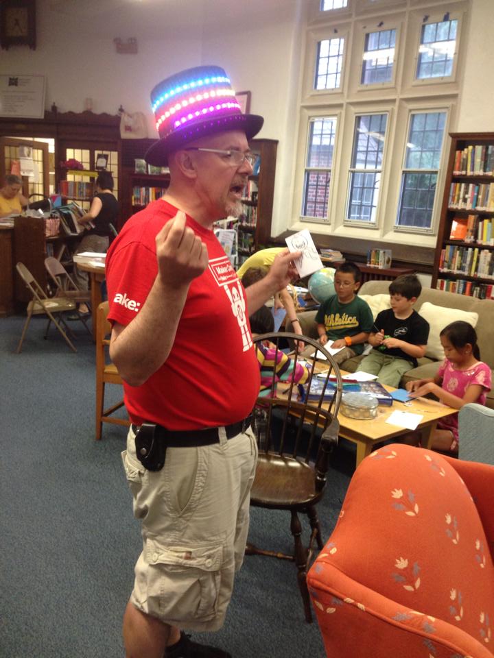
I led a paper circuits workshop at the Auburndale Community Library, and I thought I’d share a few thoughts in case you’d like to try it on your own. By the way, all the photos in this post are by our host Dana Hanson, a good friend and one of the key volunteers that keeps the Auburndale community library going (with no municipal support!)

I let the library know that it would be ok for all ages, but if kids were under 7, a parent should stay to help. We got lucky in that we had a couple of parents who either got it right away or picked it up very quickly and they were able to help tremendously.

The first I saw this idea was on the MIT High Low Tech site and they have some good pointers. They use surface mount LED’s but they are quite difficult to tape, so we modified with regular LED’s.

Setting the basic rules: Lithium batteries need to be recycled (and don’t eat them…), What is a circuit (relating to circles…) watch out for short circuits, polarity of LEDs. This circuit is very forgiving, the internal resistance of the coin cell (we used CR2032) means you don’t need a series resistor to limit current for the LEDs, and also means that short term short circuits don’t destroy the battery immediately or cause a fire!

Some Clown

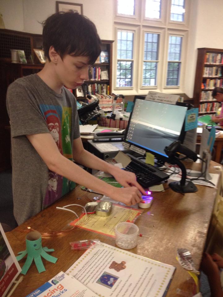
We set up a station to hand out materials at the circulation desk. Next time, I think I might divide it into several stations. The most time consuming part was letting them pick which LEDs to use. You could either limit it to one kind, or spread it out a little. You could have people just pick them from bins on the table, but sometimes people take too many. (It wasn’t a problem here….) My son’s Mason and Grant assisted me both in preparing and in debugging people’s circuits, and were indispensable.  25 Kids with about 80% of them needing help would be too much for one person.

Critical help

One of the mothers came up with a good way of making the connections more reliable add copper tape under the leads of the LEDs as well as on top.
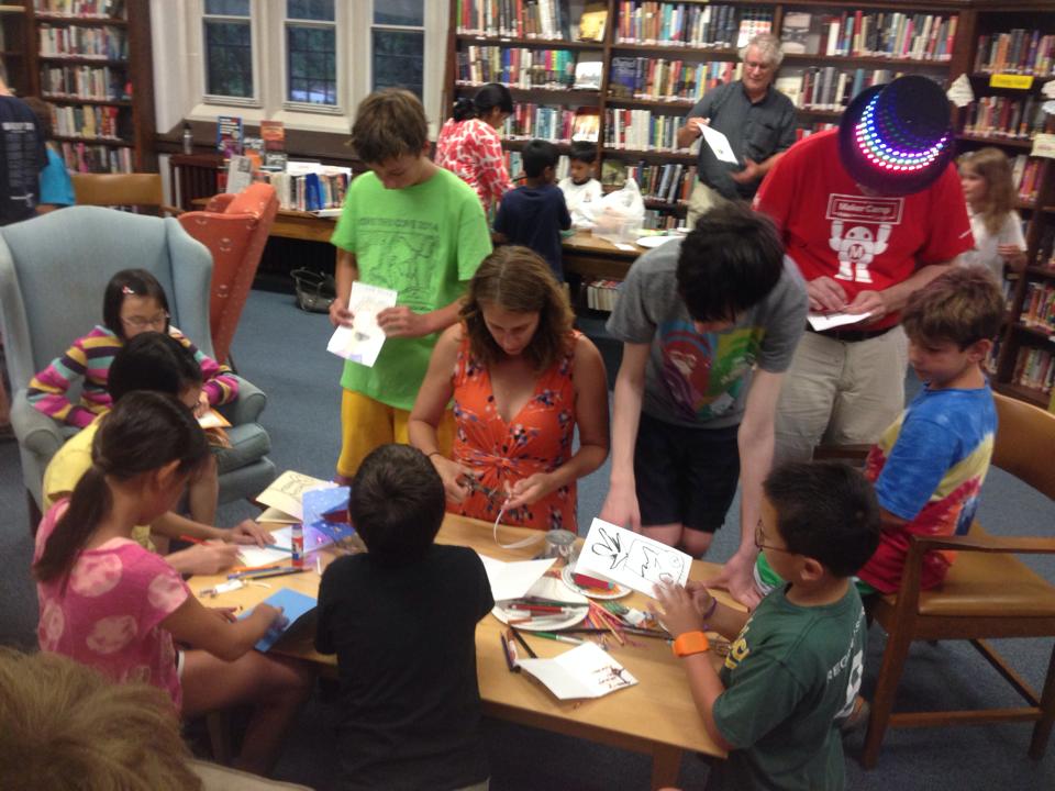
Hard at work

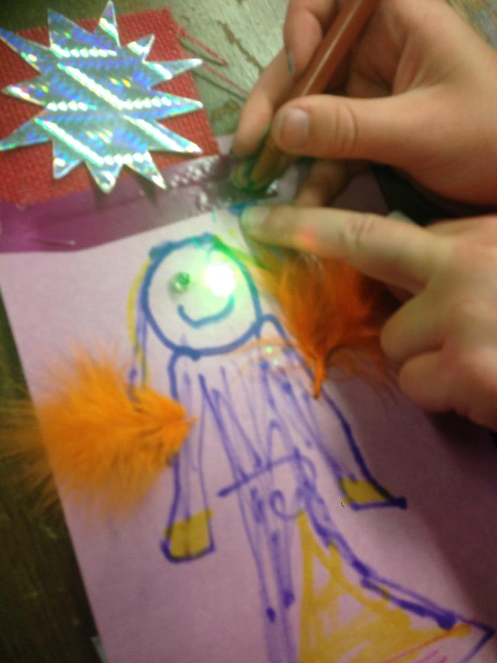
Beautiful artwork

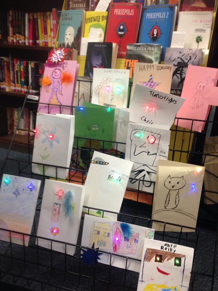
One of the book racks made a nice display for the finished work.Gallery of creations


Free and Open Source Data Service from Sparkfun

datasparkfun

Sparkfun launched a free cloud data service for your devices. It’s limited (rolling last 50MB) but also open source so if you want to roll your own you can do as much as you want!
This is an example of how doing a service and open source can benefit you. As they say

Our hope is that you buy a SparkFun widget to connect your next beehive.

It looks easy to use, and besides making it easy to put your own sensor data up, data from all other users is public, making it available to data scientists and hobbyists.

I’m looking forward to trying it out, and if I do I’ll share here!


NovaBooth – Improving the Open Source Photobooth

NoVa SnapAs you may have read here previously, we (the Wyolum Gang) created a photobooth for the Open Hardware Summit, for the purpose of customizing the e-paper badges we made for the conference attendees. This processed the pictures into a small black and white image for the e-paper badge, and saved it onto the badge’s micro-sd card.

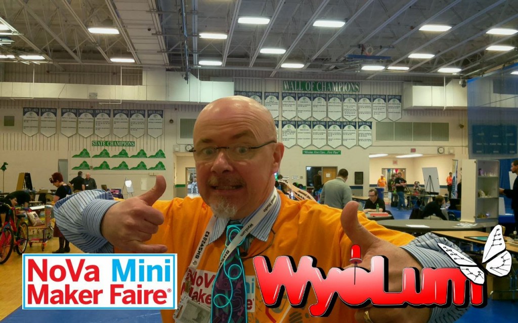
I was headed to help out at the Northern Virginia Maker Faire, and thought it would be fun to update the photobooth to take full color pictures, upload them to the Internet and offer to email them to friends and relatives.

The email message and logo files are easy to add and customize.

For basic construction, visit the original post, but download the new software here:

github: https://github.com/wyolum/NovaBooth

The fabricate directory has the laser cut files, arduino for the AlaMode Program, and scripts for the python photobooth code.

Edit custom.py to customize the email subject and message. config.py contains the authentication information for the google email and posting accounts. You’ll need to set up application specific passwords for this on your google account. You can use the same account, or separate.

Wireless keyboard, had to add a powered hub.

Problems

  • External powered hub was a pain.
  • Proto-screw shield was too heavy and lifted off
  • Some of the nuts came loose in travel.

Photobooth 1.5

To solve the first problem, I determined to replace the non-powered hub in the photobooth with a powered one.  I tried to add power to the unpowered hub, and this worked at first, but then took out the power supply and made the raspberry pi flakey too.

Scratch that, I ended up using a small belkin powered hub. I y-connected the power to it.
I noticed that  a convenient orientation put  4 ports right next to the edge,  so I cut a hole in the box to expose them.

Luckily AlaModes ship without shield headers installed, so I replaced the AlaMode and protoshield with an AlaMode that was directly soldered to the button, led-strip, power and ground.

I updated the AlaMode’s photobooth program directly from the photobooth. Apparently the new AlaMode’s pullups weren’t as strong, so I added a 5.7k pullup to the Button Pin.


Instant Party for Arduino Day!

[youtube]http://youtu.be/65PD9Plcd30[/youtube]You Do It Electronics in Needham asked me to help out with their Arduino Day celebration on Saturday March 29, and I wanted to make a nice Arduino demo that uses parts that they sell, relatively simple, and Fun! You Do It also sells DJ and disco equipment, so I thought what would be better than Arduino controlled Disco lights and Music?

Here are the Parts I chose:
Sparkfun Motion sensor (to trigger the Instant Party)
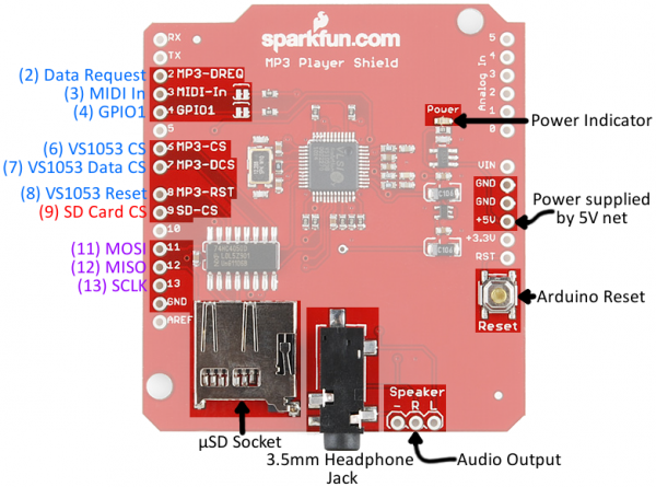
Sparkfun MP3 Shield
Arduino
Sparkfun proto-screw Shield (to make it easy to hook up.)
Power Switch Tail – turn on the disco lights

You’ll also need a micro-sd card and some music. I chose some Creative Commons Techno from Soundcloud:

https://soundcloud.com/captain-karacho/city-17
https://soundcloud.com/captain-karacho/brainwreck

First, we need to find out what pins are in use in the MP3 Shield so we can figure out where to hook up the motion sensor and power switch tail.
The easiest way to do that is by looking at the schematic, or this page at Sparkfun: https://learn.sparkfun.com/tutorials/mp3-player-shield-hookup/hardware-overview
MP3 Shield hookup

Digital Pins 5 and 10, and Analog Pins A0-5 are all free.

I used the analog lines because they are close to the power and ground pins for both the power switch tail and the PIR motion sensor.

Because the PIR output is open collector, I use the internal pullups on the Arduino.

Git the code here: https://github.com/osbock/InstantParty


Maker Workshops calendar

I’m very fortunate to be working with a number of wonderful libraries (and librarians!) doing maker workshops. I put together a google calendar of the upcoming workshops I’m leading. You’ll be able to find it in the menu on this site, and here’s a copy for your perusal now!

A Brief detour into Cryptocurrency

dogecoinI attended a meetup of HackBoston, run by Abby Fichtner (HackerChick) from the Harvard Innovation lab. Project 11’s Reed Sturtevant wanted to learn more about Cryptocurrency, so he started experimenting and shared the basics with us at the meetup.

Most people have heard of BitCoin, but Reed shared that it’s so hard to mine now, it’s very difficult to experiment without putting in real money. He found DogeCoin as a fun, and lighthearted alternative. Often used as a +1 or like tipping system for blogs and on social networks.

Pre-work was to set up wallets before the meeting, as they take time (about 5 hours) to synch with the network.

We each recieved 2000 dogecoin at the beginning of the meetup. Then we learned the basics of how to use addresses (essentially the destination of coin transfers. We transferred money to each other.

While doing this Reed went over the basics of cryptocurrency, which I won’t cover here, but the wikipedia article covers it pretty well.

We also created accounts at tipdoge.info which lets you send DOGE via twitter. (feel free to tip @osbock)!

Intro to Mining

If you read the wikipedia article, you know that transactions are verified by a cloud of contributers performing cryptographic checks distributed across the Internet. “Miners” are rewarded both through the creation of new “coin” (which slows) and the distribution of transaction fees. Without special hardware, your chance of winning a race to solve the puzzle that is a cryptocurrency transaction is minimal, so mining pools were created to distribute the work and the reward.

We created accounts on the mining pool site dogehouse.org, created workers (essentially addresses within the pool for your mining processes to communicate) and downloaded and configured mining software.

I recently got a nice “gaming” laptop from Lenovo, because it offered very good price performance, plus it has an Nvidia graphics card which I wanted for computer vision experiments.

Because Nvidia graphics cards contain many parallel processing cores, and Nvidia has released an API that allows their use for general purpose parallel computing, they are often employed for mining.

The Experiment

Following instructions from dogehouse.org, I set up cudaminer (cuda is what Nvidia calls their processing cores) and another instance running the pooling cpu-miner to take advantage of the native cpu cores of my laptop’s i7.

Each mining process (cudaminer and pooling-cpu-miner) were configured to report to a “worker” setup at dogehouse.org.

I then mined overnight to determine:

  1. The kH/s (thousand’s of hash per second) capability of my laptop
  2. How much doge/hour I could mine
  3. Electricity cost of running the computer. (determined with a P3 Kill-a-watt)

Using an exchange rate, I converted into dollars to see if I could mine more doge than the electricity cost.

The Results

The cuda miner was reporting an average of around 80 kH/s and the cpu-miner around 54 kH/s

In 14.07 hours I mined 261.229 Doge for 18.57 Doge/hour, or $.0147/hour (at an exchange rate of .00079$/Doge.) Power usage was approximately 1.4 kWh, which I calculated to cost $.19.

Projecting out to a month, at  134 kH/s, I’d earn a whopping $.95 (and lose a lot of the computing bandwidth of my laptop!)

I could invest in a fancy graphics card and dedicate a computer, but I imagine it would cost even more electricity.  So, I would say  overall, a negative return on investment.

This apparently became the case for bitcoin as well, until people developed specialized hardware that gives a high H/s rate at low electricity usage, first using FPGA’s and then specialized ASICS (Application Specific IC’s). Doge uses a different Hash algorithm than Bitcoin, so you can’t use the now ubiquitous ASIC mining equipment optimized for the SHA 256 algorithm. There’s a new ASIC to be released soon that supports Doge’s (and litecoin, and others) Scrypt algorithm, and by extending my calculations, the cheapest of these devices ($119) would pay for itself in 3 or 4 months.

I’m going to try to get one to see. Of course, all these calculations are based on assumptions of stability (exchange rate, mining rate etc.) which are completely unreasonable. Still it’s fun to try!

EL Wire workshop

I did a couple of EL wire workshops at the Newton Free Library yesterday. It was a great time, and I think everyone left quite happy. Here’s how I prepared, and what we learned during the workshop.

If you aren’t familiar with EL-Wire, or Electro Luminescent Wire, it’s a plastic coated wire that lights up when fed a fairly high voltage (~100V) high frequency AC signal of about 1000hz. (There’s a little more to it, check the wikipedia entry for a nice diagram of the internals…)

I ordered 55 Units that each had 3M of elwire, prewired, and a control unit that runs off of two AA batteries. I got them from an ebay seller (Sure Electronics) in order to get a good price. You can also buy them from domestic sellers like Sparkfun, but they end up being about 2x the cost. It’s good if you can talk to the Seller, as Sure told me that they sold two types, a less expensive one that was dimmer and a more expensive one that is brighter. I’m not entirely sure which one I got! The different colors were definitely different brightnessEL-Tie, with Greenish yellow being the brightest, and red/pink being quite dim in roomlight.

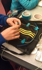
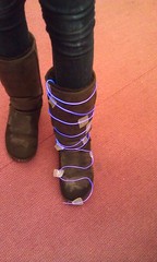
I wanted to create an example, so I sewed a segment onto a tie.

A couple of pointers here:

  1. Figure out where you want the battery pack to go.
  2. Start your layout from the battery end. It’s easy to cut off the other end (and safe) but it’s hard (but not impossible) to reconnect wires to the driver end.
  3. Scissors aren’t really strong enough to cut the el-wire, you should have some wire cutters on hand
  4. You can either attach as you go. or tape down your design. Most people felt that this created a more fluid design, but may make it difficult to properly lay out a complex design.

Methods of attachment:

  1. Tape. One kid used a type of very sticky first aid tape to tape his design (the Pi sign in the gallery below) to the back of his shirt. It made a really conforming design with a flat background. This wouldn’t look very good on the front of the shirt.
  2. Hot Glue. Be careful here, but it’s good, especially on things it’s hard to poke a needle through. Lower temp glue sets more quickly, but high temp is useful for attaching to some surfaces. If you are sloppy, it shows, but you can unglue the wire (still leaving a blob) by using a heat gun or hair dryer
  3. Sewing. This is the most invisible and elegant, but also the slowest and most work. If you use transparent thread, it’s even more invisible, but you’ll need to know your fisherman’s knots.
  4. Cable Ties: This is useful for attaching to, say a bike frame, or other tubular structure.

EL-Party time!

Last, make sure you turn off the lights at the end! We also had a dark closet available to test before we turned off the lights!

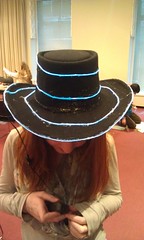
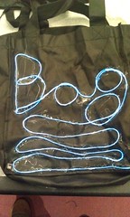
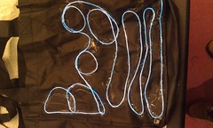
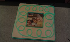
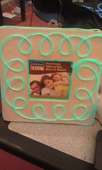
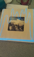
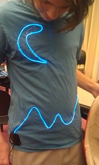
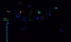
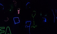
Here are some examples of the creations the kids made.

Simple 3D printing design activity


A lot of  libraries and schools are getting 3D printers, and also, if you personally have one and want to show it off, it’s hard to have people do things in a reasonable amount of time. 3D printers are just inherently slow.

One activity I came up with that allows you to do personalized 3D printing, is to, well, do 2D printing!

We’ll learn how to take some characters, make them into a flat 3D object that can be printed quickly.

This little logo printed in about 2 minutes on my Printrbot Plus.

We’ll be using inkcape (a vector drawing program) from http://inkscape.org, and OpenSCAD (a 3D drawing language) from http://openscad.org. Download and install (they are both free and open source!)

Here’s a video walk through, but details are also written below.

[youtube]XnpnsKFmvZE[/youtube]

Step by Step:

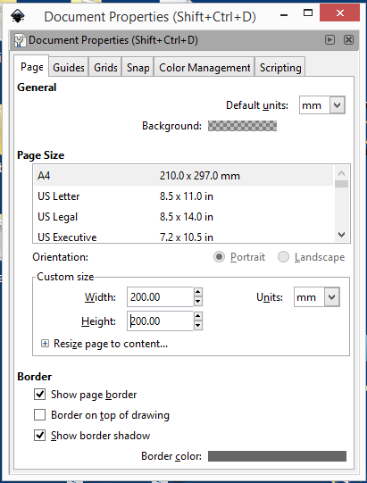
Open a new document in inkcsape. I like to change the document properties to use a real measuring unit, so I  can tell how big things are. Change the default units from px to mm, and the size in mm units to your print bed size. In my case 200×200.

Document Properties

Using the Text tool, type your name. I use 72 pt (about an inch or 25.4mm tall) and a font that is fairly blocky. If you want to print larger, you can use more filigreed fonts, but for this exercise, the point is speed, so we need something that will print well small.


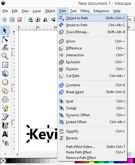
Select the name using the arrow tool, and then path/object to path:

object_to_path


Next click on the second icon down (below the arrow) that is edit path by nodes.

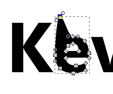
We’re not quite there yet, as we have a path, and we need polygons. Paths include things like splines and other curves. If you grab one of the handles you can see we don’t have straight lines.

It can be a little frustrating working with some of these tools, but there’s a secret OpenSCAD only understands polygons in a DXF file. If you have any splines or arcs, it just ignores them, sometimes giving a warning, sometimes not.

splines-bad


Shift select all of the letters while in path editing mode.

The key to converting any 2D vector drawing is to make sure to select all the segments and click the convert to lines button. Curvy letters like the lower case E in my name will reduce to angular uglies, so , you can add points by clicking the add points button a couple of times.

Next, click on make selected segments lines (make sure all the nodes are selected. If they are grey, they are not selected.)

Next, it’s a little tricky. Click on the second letter in path edit mode, switch to select/move mode (the arrow) and move the letter to touch the first one. Repeat. For the i, I moved it down so the dot was also touching.

At this point we have a bunch of polygons, and OpenSCAD may or may not be able to render it. You can make sure by selecting all the paths, and then perform a Path/Union menu function to simplify the shape.

It’s best to move the whole thing down to 0,0. You can do this with the mouse, or just type in the x,y box.

Next, save it as a DXF file (not the default SVG), in the same directory where you’ll store your openSCAD file.

Then it’s a simple matter of linear_extrude(height=2)import(“kevin.dxf”);

The dxf file has to be in the same directory as the scad file, so you have to save the scad file first before you run it.

It’s probably best to select print quality settings that don’t take too long, but still look ok. You can also influence the print time by extruding at a shorter height, but I think one mm is about the minimum for something you can remove without breaking