All posts by Kevin Osborn

About Kevin Osborn

I’m a Maker and ardent amateur educator. I also love to create art, hack electronics and do geeky activities with my kids.

DIY Rayguns!

IMG_20160117_244535475

I’ve been going to Arisia (one of Boston’s Science Fiction Conventions) for several years. I always have a great time, and it always amazes me the amount of volunteer effort that goes in to providing amazing programming for everyone. This year I wanted to give something back so I came up with the idea of people building rayguns.

(NOTE: My extra kits are available in my etsy shop: https://www.etsy.com/listing/265475569/diy-raygun-kit)

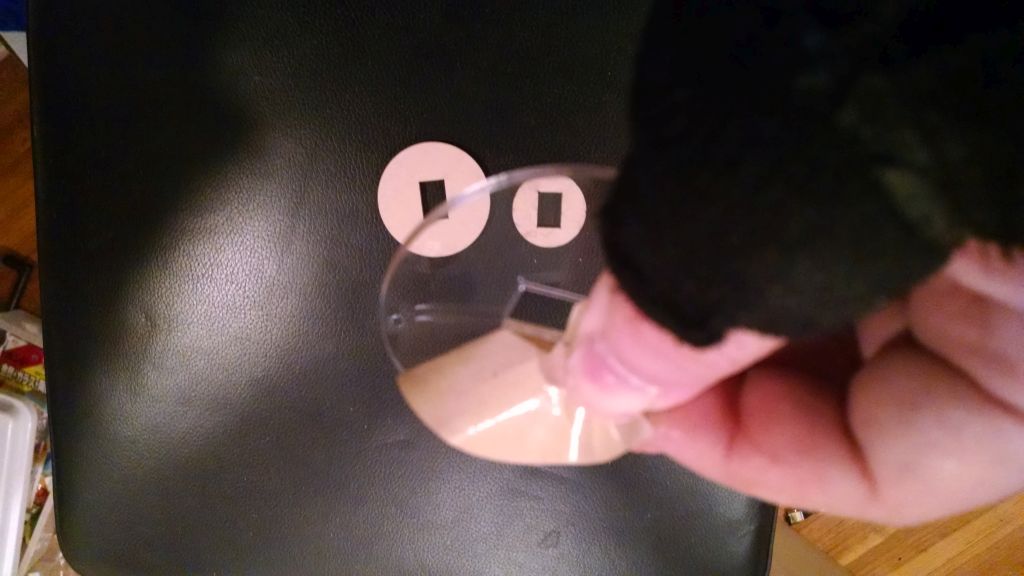
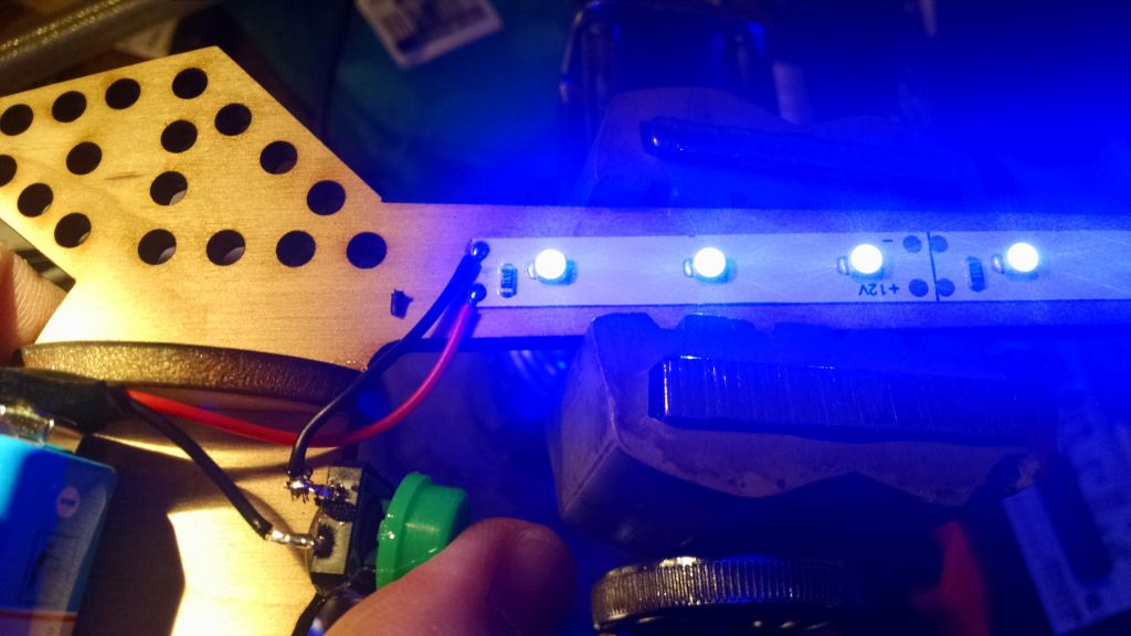
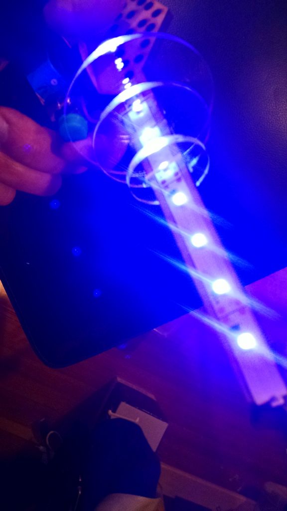
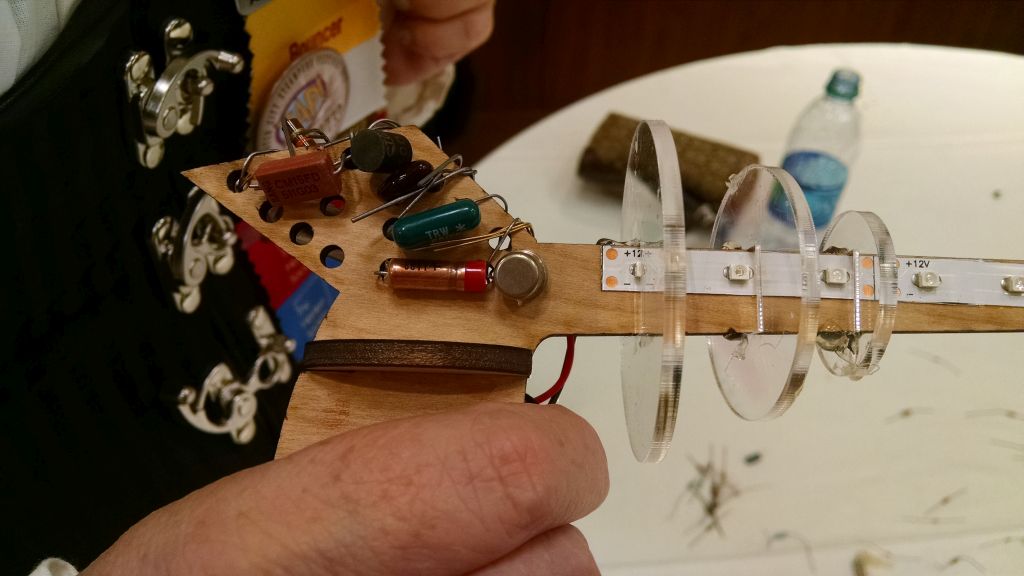
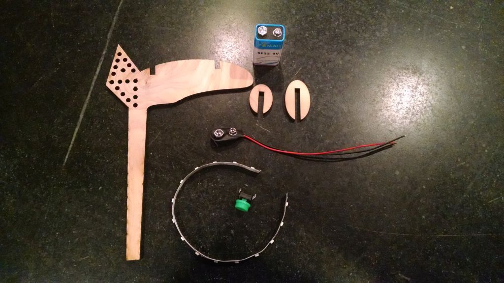
Regular LED strip is super cheap when you order it from China. It normally runs off 12V, but a 9V battery lights it up just fine. I created a simple laser cut frame to put some LED strips, and then some cool laser cut acrylic disks to give it that groovy 50’s raygun look.

I bought most of the parts myself, but special thanks goes to my friend Jeremy Green at Charles River Maker for donating Laser time for cutting the kits. He’s your goto guy for design, prototyping and digital to physical services with laser cutting and lots of 3D printers!

IMG_20160124_200031275

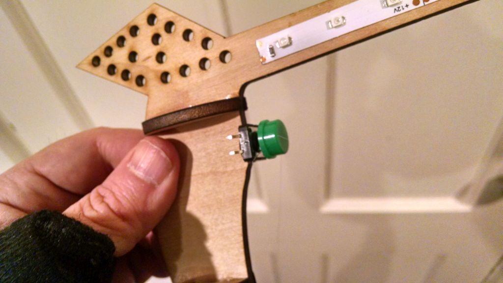
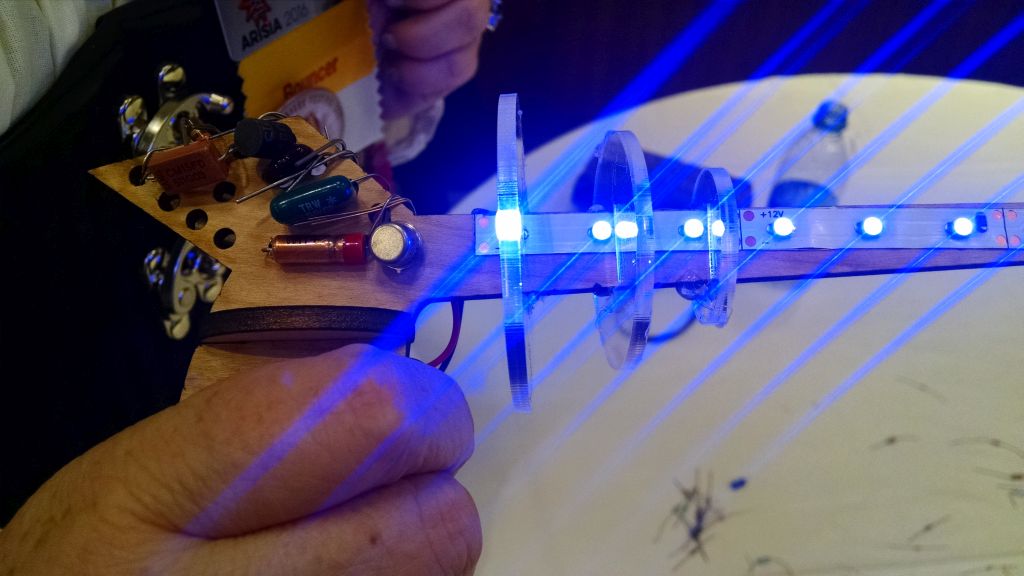
A switch makes the trigger, and there’s a fin with holes to add decorations.

IMG_20160124_202035981

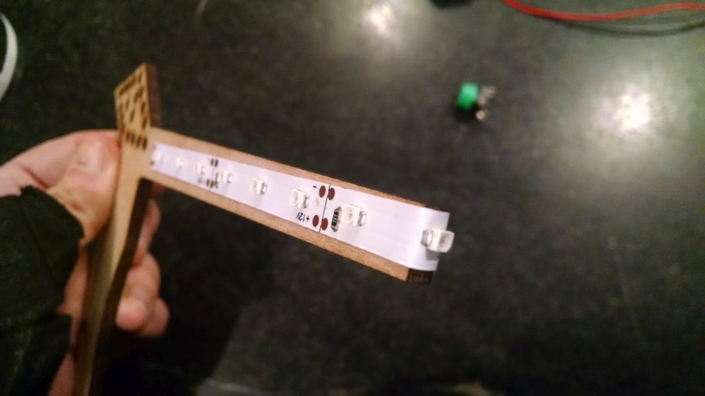
First cut a strip of LEDs. Mine consisted of groupe of 3 led sections.. Cut a strip of 5 sections, two sections on each side and one straddling the middle:

IMG_20160124_200123002

next glue on the handle “dimensional” bits. These are mainly to make a recess for the battery, and maybe wrap the handle. Super glue works pretty quick, but you could probably use wood glue or whatever is appropriate for your frame:

IMG_20160124_200915995_HDR

Glue the trigger button on, (kindof low, as the disks are pretty close. Actually I moved it down abit after I put the disks on (later step)

IMG_20160124_201644540_HDR

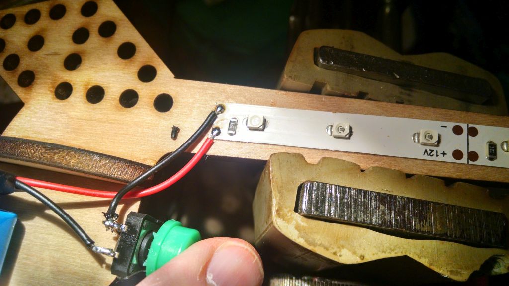
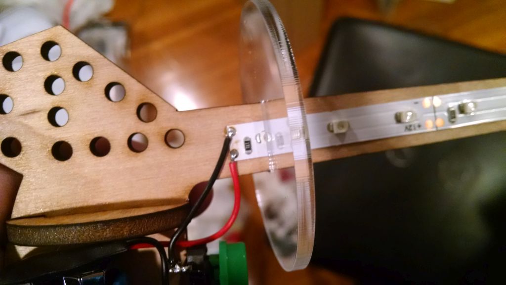
Line up the battery clip and shorten the leads to connect one end (I chose the red, positive wire) to the positive contact on the LED strip. A small wire went from the negative contact to the switch and the other lead of the switch to the negative lead of the battery clip.

IMG_20160124_201656322

Test, viola!

Next line up the disks where they fit. back them off and put a drop of superglue where each disks goes in order.

IMG_20160124_202344870

IMG_20160124_202812456

The source files for laser cutting are at: https://github.com/osbock/Baldwisdom/tree/master/DIYRayguns

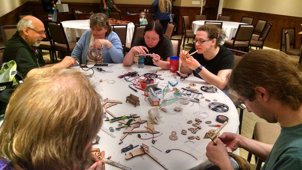
And now a few pics from the workshop at Arisia!

IMG_20160117_244513394_HDR

IMG_20160117_244050950_HDR

IMG_20160117_244531403


Parametric Littlebits Mounting system

TL;DR version: I got to borrow the littlebits synth kit, and created a parametric version of the mounting board. The source files are available on github: https://github.com/osbock/Baldwisdom/tree/master/LittleBitsMounts

The Newton Free Library applied for and got a cool LSTA ( Federal Library Services and Technology Act) Grant to do a bunch of STEM related programs, and I have the honor of doing a bunch of coding and robotics workshops there over the next few months.

They got a bunch of cool new equipment to run these programs including Finch Robots, Arduinos (Sparkfun Inventors Kits), a KIBO robot, and … wait for it… a bunch of Littlebits sets. NFL Assitant Director Jill Grabowski was kind enough to lend me the coolest littlebits set: The Korg Synth kit.
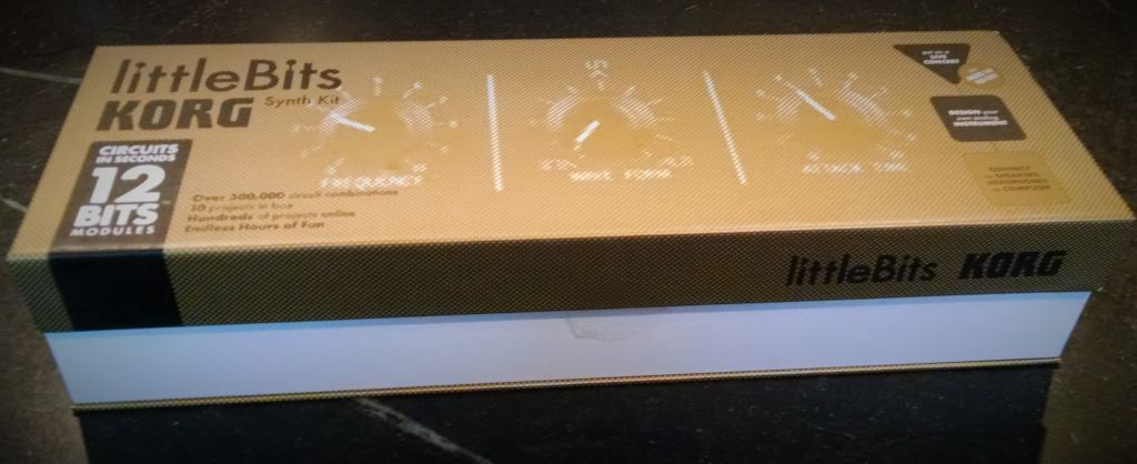
korgset


If you aren’t familiar, they are modular electronics blocks that snap together with magnets. Unlike earlier “electronics construction sets” these are pretty foolproof, well thought out modules instead of just individual components. As Founder Ayah Bdeir says ,

AT LITTLEBITS, WE ARE ON A MISSION TO DEMOCRATIZE HARDWARE BY EMPOWERING EVERYONE TO CREATE INVENTIONS, LARGE AND SMALL, WITH OUR PLATFORM OF EASY-TO-USE ELECTRONIC BUILDING BLOCKS.

Unfortunately the thing that makes Littlebits easy is also it’s greatest weakness: The magnetic connection system.

Especially when making something you have to manipulate (like a musical instrument), they tend to come apart, you lose power, etc.

Now some of the other (more expensive) sets come with mounting plates (that you can also buy separately. I didn’t have one though, but I do have a laser cutter and a 3D printer. How hard could it be? Well, the devil is in the details.

First I looked to see if it was already done. Thingiverse (I know boo….) has a few designs, including some by littlebits themselves, mostly specific component mounts.

Rex Brodie posted this cool clip that fastens adjacent modules together.
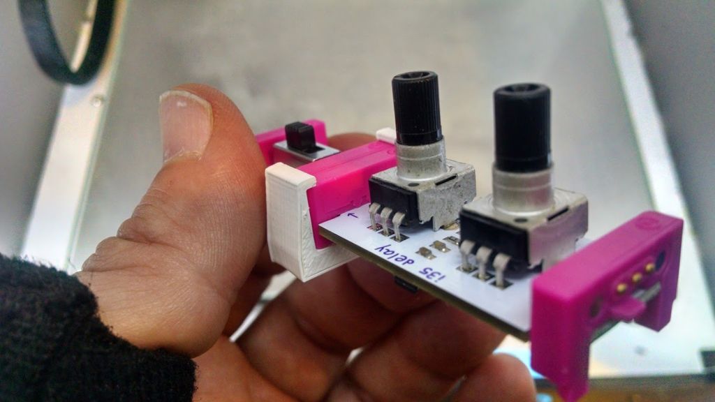
clips

It works pretty well (very solid) but it was difficult to put the two bits in without pulling and pushing and putting a bit of strain on the boards. (Especially scary when the ‘bits are on loan).

I tried just measuring and cutting holes with my laser, or a simple model with Open SCAD but I just couldn’t get the spacing quite right.

Thingiverse user Kris Kitchen had posted this design:
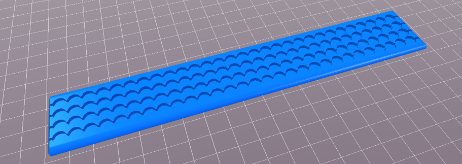
littlebitsgrid

which I printed and actually worked quite well. Only problem was, it was an STL (Surface Tessellation Layer) file, and thus not easily modifiable. I wanted wider, arbitrary shapes, etc!

I could however pull Kris’s design into OpenSCAD, and do a trick to measure the “holes” and spacing.

This little bit of code:
[code]
projection(cut=false)difference(){
translate([0,0,-41])import(“LittlbitsGridthin.stl”);
translate([0,0,-10])cube([250,40,10]);
}
[/code]
cuts off the bottom so the holes will show and projects the outline in 2D.
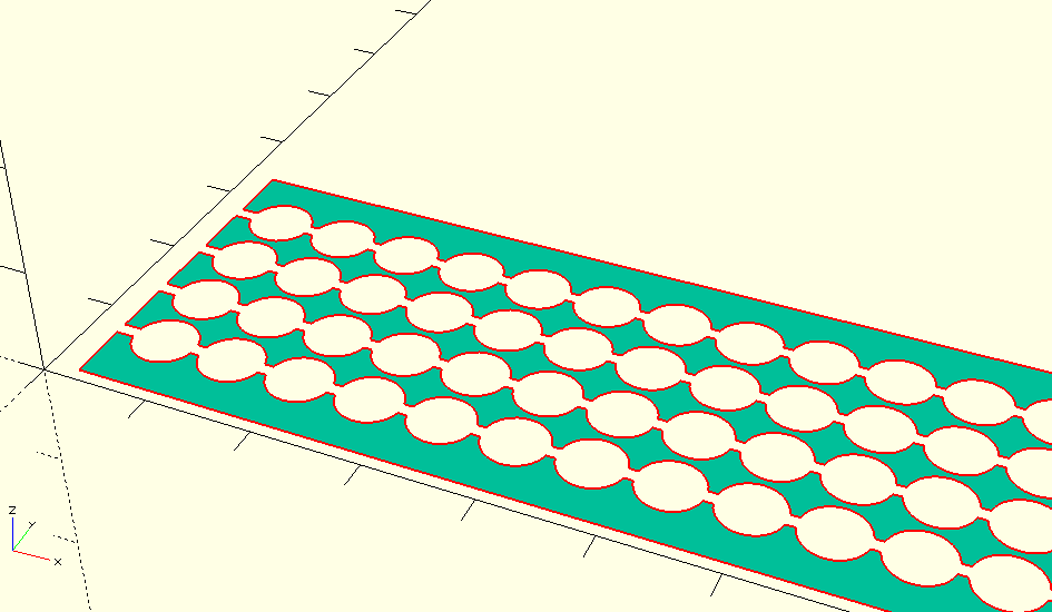
projection

I then exported this as a DXF file, and used inkscape to make measurements.

If I haven’t lost you by now, the part you are waiting for, the measurements (which I couldn’t find anywhere after much googling!)

  • Holes: 6 mm diameter
  • Spacing (edge to edge or center to center): 6.63mm
  • spacing is also 10.5% of hole
  • 1.294mm knockout line

The percentage bit is important (I calculated it, 6.63/6) if you are designing in inkscape because that is how you do a grid of evenly spaced objects.

I made a couple of attempts at a laser cut version, but it was very brittle, and I didn’t take into account the laser’s kerf (width of cut)

The 3D printed version came out pretty well, but the holes were a bit too small, so I enlarged them by .2mm (.1mm on the radius). and it worked perfectly!
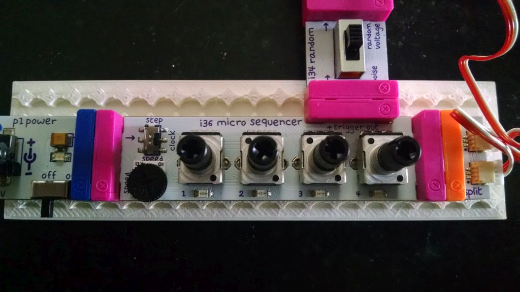
littlebitsmounted

Now we can make mounting boards in any shape!
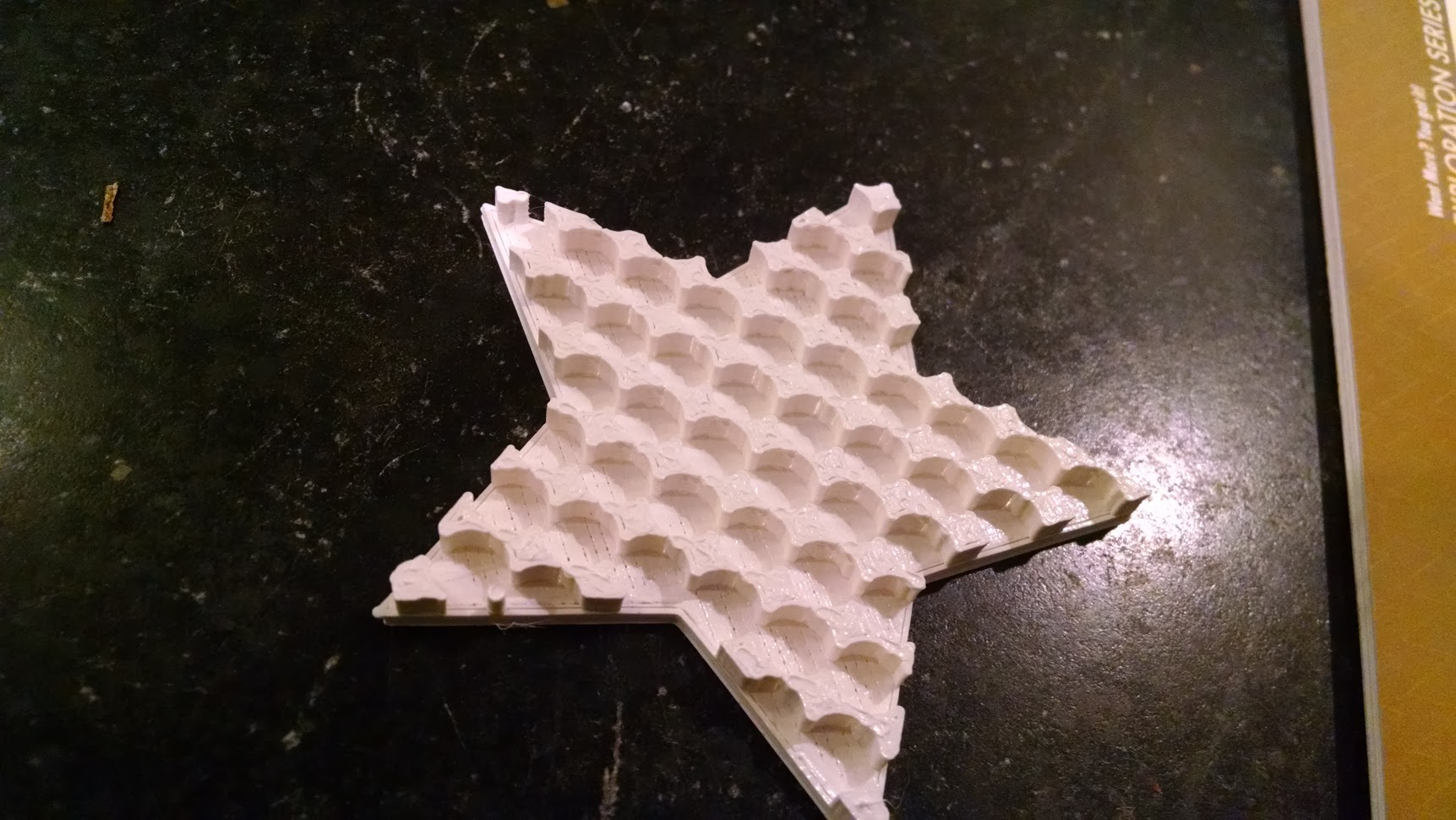
star

The source files are available on github: https://github.com/osbock/Baldwisdom/tree/master/LittleBitsMounts
Is 3D printing good for anything practical?

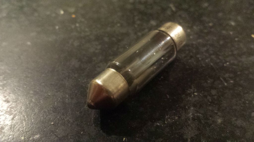
When I took my Mini Cooper in for it’s annual state safety and emissions inspection it failed because one of the tail lights was out, and the license plate lights were, well really out. One of the lenses had long ago fell out, and the other bulb was dead.

20151119_175622When I looked on line, the cost for a couple of lenses and the bulbs was greater than a complete unit with LEDs (never replace again!) so I ordered a pair from ebay. They came, but the contacts wouldn’t make connection with the bulb holders.

I communicated with the Ebay seller, and they were great, offering me a refund or to find the right bulbs for me, but I was impatient.

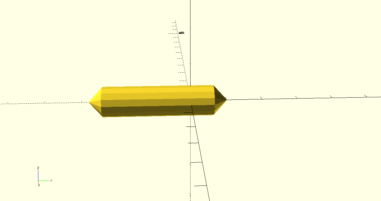
I decided to make a bulb proxy and solder wires between it and the new LED fixtures. It only took 10 minutes to whip something up in OpenSCAD:

scadimage

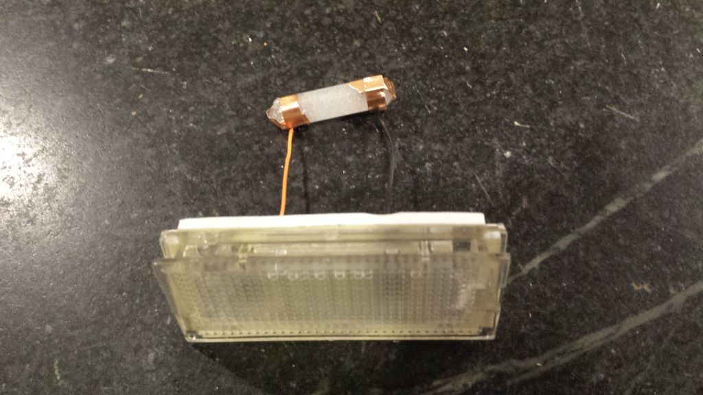
It didn’t have to be pretty it just had to fit and hold the contacts in place. For contacts I wrapped the ends in copper tape, and soldered wires between those and the light fixtures.

20151119_173502

Note, that it’s easier to solder to any delicate surface if you use liquid flux.

The result was fantastic (pay no attention to the filth on my car….)

20151119_182044

Hopefully it will pass inspection tomorrow. Of course if I didn’t have all this stuff at home, it totally wouldn’t have made sense to do this, but I do, and it was actually a fairly fun and easy project.


Arduino Workshop and Arduino Resources page

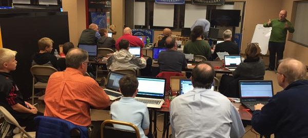
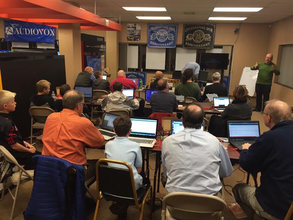
youdoit-arduino class

Had a full house at an Intro to Arduino Workshop at YouDoIt Electronics in Needham last night. Getting ready for this prompted me to start up an Arduino Resources page and update my Intro to Arduino Presentation (which, unfortunately I didn’t get to use due to technical difficulties…)

YouDoIt Electronics is a terrific local resource, carrying tons of Sparkfun and Adafruit products (as well as tons of mechanical and electrical parts, educational toys, AV equipment, you name it!) Thanks Melissa and John for sponsoring me!

Interactive Wall at the Duxbury Free Library

I was Maker in Residence at the Duxbury Free Library in August, where I worked with Teens and some adults to create an Interactive wall for display at the Library.

I met Teen Librarian Ellen Snoeyenobs at the first Make a Makerspace conference at the Artisan’s asylum several years ago, and we’ve been collaborating on bringing more maker activities to her library over the last 2 years. She has an excellent blog reflecting on their successes, failures, and tips : http://librarymakerspace.blogspot.com/

She has her own excellent video here:

Lessons learned

  • Something for everyone. There are art activities for those who won’t go near tech stuff, and plenty of wiring and coding for the techies. Girls, boys, adults alike found something to do.
  • Drawing on skills learned in the past helps to get things done. We did one session on Arduino at the beginning, but in the end, those who already had Arduino experience ending up contributing most in that area.
  • Include a variety of activities. Kids who liked 3D printing and design did various bits to glue on, and use, including a spider that goes up and down. The 3Doodler was used a lot to add decorative elements, as well as enhance some of the 3D prints. And of course, Arduino brought it all to life.
  • Think Off the Wall. Ellen was originally inspired by an interactive wall she saw at MIT. The library, however, wasn’t too keen to be hacking into their existing walls. Ellen came up with the idea of a portable partition, and I helped select one (made of poly-carbonate) that we could drill. It had the additional advantage of being semi transparent, so we could mount our fireflies (addressable LEDs,) behind the wall.
  • Surprise learning. There were all sorts of bonus learnings, including how to scale a drawing up using a grid!

Technology

  • The library had previously received a grant that enabled them to buy a bunch of Spark Fun Inventors kits. We used velcro to attach the Redboards and their attached breadboards to the back of the wall.
  • We used a PIR motion sensor to trigger the bird moving, and cheap Chinese HC-SR04 ultrasound distance sensor to light up the peacock’s tail as you waked closer.
  • WS-2812 LED strips provided bling for both the peacock’s tail and the fireflies.
  • Birdsong was provided by a Sparkfun MP3 Shield
  • Movement was done with micro servos, and one continuous rotation servo from parallax.
  • The shifty eyed fox was implemented by a great design from Dampboot on Thingiverse

Come see it!

Our Grand Reveal of the Arduino Interactive Garden Wall will take place on
Thursday, September 10th at 4 p.m. on the Upper Level of the Duxbury Free Library.

We’re hoping some of the Teens as well as adults who had a hand in making it will talk about the experience.

MacGuyver Copter Part 3: Success!

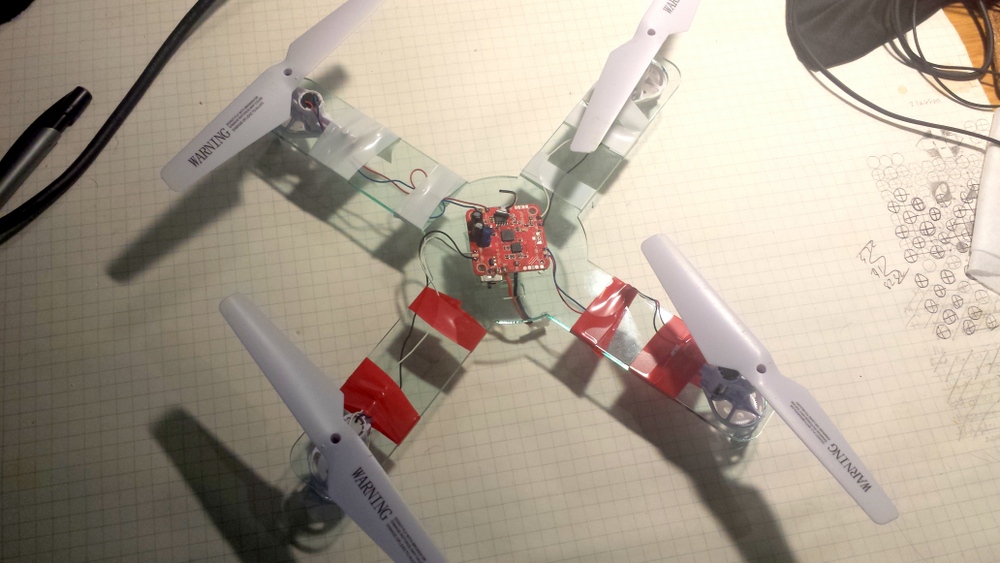
If you have been following along, in Part 1 and Part 2, I was trying to build a simple, cheap and easy quadcopter from spare parts. Well, the simplest methods failed, time to get out the laser!. Acrylic isn’t the best material for a quadcopter frame. It’s relatively heavy, and fairly brittle. but it’s  easy to cut in a laser cutter, which I happen to have, courtesy of Wyolum.com.

20150721_215248

Did it work? Well, it didn’t flip over, but started spinning a bit in place.  When I picked it up with the props going, some of the air was blowing up! I somehow got the ordering and placement of the motors wrong. I cracked open my original X5C (wow, that’s a lot of screws!)

I fixed the wiring, and then it flew! About 6 inches off the ground! I noticed that the props were rotating about 1/4 of a rotation over the body which means a lot of backwash, but the main problem is revealed when I weighed it.

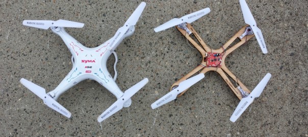
The original Syma x5C with camera and battery weighsin at 97 g.

Version L1 of the MacGuyver Copter: 122g. Flew about 6 inches above the ground.

I created a new version with more or less rounded rectangle arms, and a circular central platform. I was worried because acrylic is rather brittle, and I wanted it to be strong.

20150722_174826-001

Version L2 of the MacGuyver copter weighed in at  106g. Flew relatively well, but inertia was killer on flips(lots of altitude loss), and battery runs down very quickly. After about 5 minutes, it was again hovering at 6 inches.

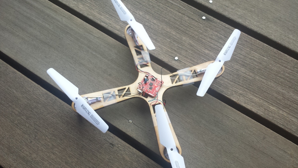
Although we think of plastic as light, acrylic is fairly heavy so I tried some plywood. All I had on hand was some 1/4 inch cheapo birch plywood from home depot.

20150722_180330


I forgot to record the wieght of this one (I think it was between 100 and 110 grams), but it worked quite well. The only problems were that my cutouts came a little close to the edge, and between the cheap plywood (voids) and those thin areas, one of the arms broke in a crash.

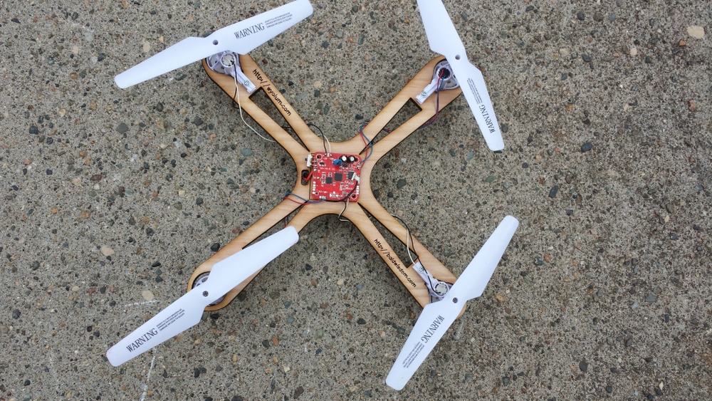
The final design simplified the cutout to be a triangle and weighs in at 84g, compared to the x5, without the camera or battery door at 88G. There are probably lighter, equally stiff materials, but this is pretty easy to do.

1-MacGuyverV3

Flys fantastic, at least to my feel It seems better than the stock version without the camera. Even though it’s less “aerodynamic, I think it handles better in a light breeze than the original, probably due to less surface area.

Here’s a (pretty bad) video of it’s flight. Trust me, it’s fun!

I also cut a frame out of 1/8 inch acrylic, but it was way too bendy, and wouldn’t take off. I think the props tended to thrust up, and bend it toward the middle, and the IMU (Inertial Management unit) couldn’t figure out a way to get enough power out to get it in the air.


MacGuyver Copter Part 2: Total Ghetto, Total Fail

Spoiler alert: in part 3, we finally succeed!

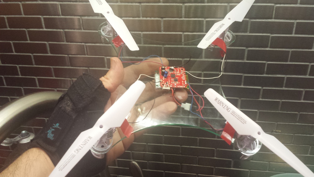
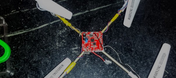
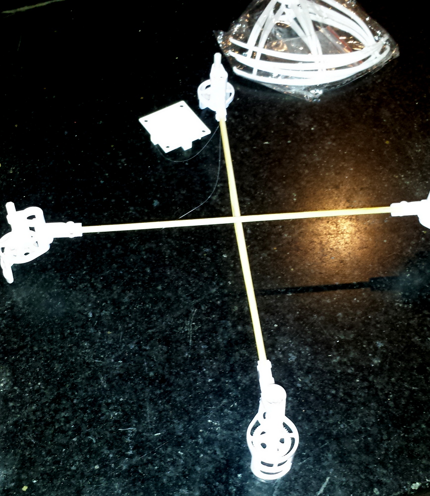
If you read the first post  you know that I was inspired by all the cheap replacement parts for the Syma X5. Also the motor mounts have all sorts of interesting attachment points, including a tube that fits a 3mm (who knew they were a standard size?) bamboo barbeque skewer. I’ve seen people bodge together quadcopters with “real” controllers but with crappy wooden frames, so I thought why not.

First I cut some skewers so the props were centered where they were in the original Syma X5. They were 9 inches center to center.

20150715_174605

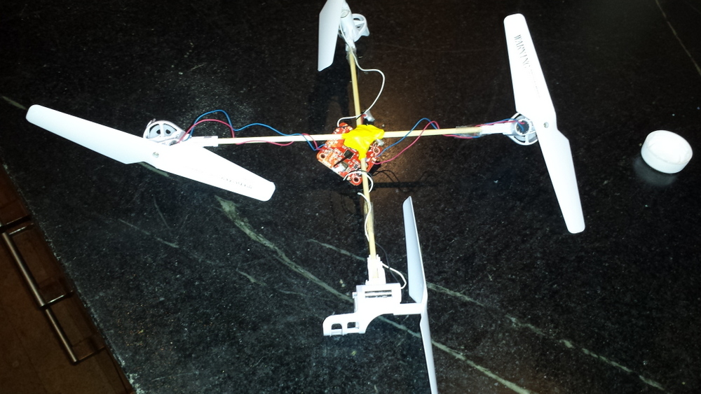
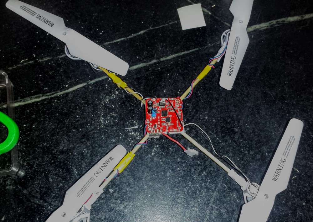
I taped it all together, with the controller in the middle. I didn’t have much hope, as  you can see the fit on the motor mounts isn’t tight, and I was afraid they would twist. I taped them the best I could but as you can see in the video it was a total fail.20150715_223808
One problem I noticed, was that I had mounted the controller board upside down. Doh! The purpose of the controller is to keep it upright!

20150716_115519

Next I designed a 3D printed hub for the middle, secured with hot glue. I found some tiny screws (scavanged from many tear aparts!) and drove those through holes in the arms and through the bamboo skewers. This time it worked better but spun. I concluded that the bamboo was twisting with the motor torque. Probably true, but later I also discovered that I had the motors mounted in the wrong place.

Conclusions: I need a sturdier frame, but still need to keep the weight light (how light, well, I find out in part 3…)

Droobots: 3D printed Bristlebots

3D printing Bristlebots gives you lots of creative options, and here’s a new way to create the bristles, or legs of the bots. More details follows the video, and the source code is at: https://github.com/osbock/droobots

Mark Peeters, came up with a clever idea for making lacy  fibrous flowers with a 3D printer, by taking advantage of FDM’s greatest weakness: the need to support overhanging structures.

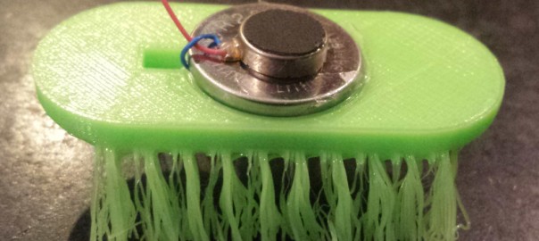
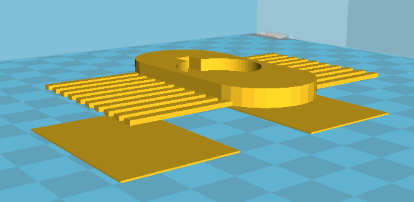
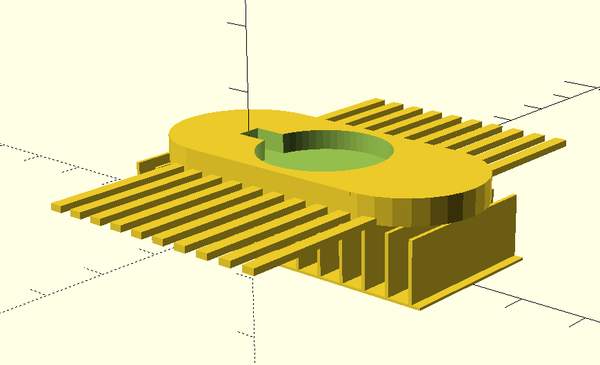
drooloop-group1 kopieTurning them over in my hand, I had the insight that they could be perfect bristles! I fired up OpenSCAD and started designing a simple bot:

The trick is that you have to let them droop down, so you have to have something in the center to hold it up, and have the legs be unsupported. I designed in support material for the body.

droobot-scad

It’s tricky if you make the support walls to thin, the slicer may ignore them. Too thick and it’s harder to remove. This version works fairly well, but is a little too heavy for my taste.


I use Cura, and I was thinking about how to use it’s native support which is very thin and easy to remove. There is an option for printing support material only when there is an overhang  on the baseplate. I put thin (.4mm) rectangles under the legs, but not under the body:

droobot-needs-supportThis works out quite nicely, and gives a speedier print.
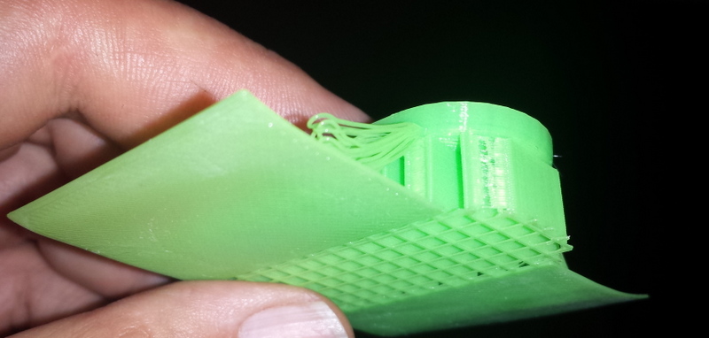
cura-suportThe other thing that’s helpful is to turn off the fan during the leg creation. You can either use the “Tweak at Z” plugin, if you use Cura, or edit the Gcode.  I located the layer where the legs started and  inserted an M107 (stop fan) command, and then when it was on a layer above, add M106 S255 (fan full on)

After printing, I use a hot air gun to soften the legs to press them down more to a right angle. This give a more energetic movement than the splayed legs right off the printer.

You can also experiment with trimming them with scissors.

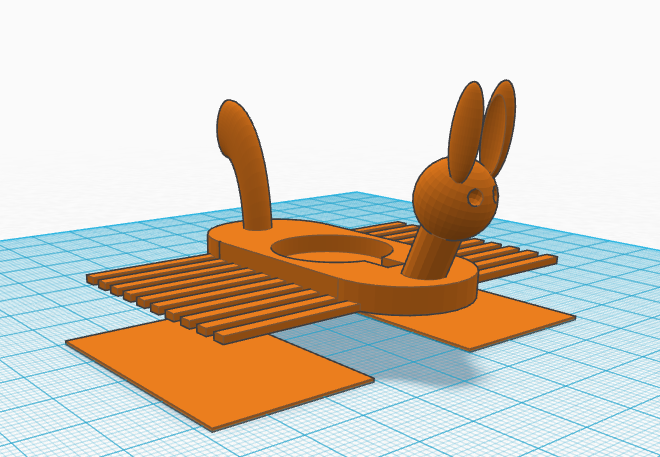
Last but not least, I imported the basic STL into tinkercad, and added a head and tail for a little more pizzazz!

tinkered-droobpt