Category Archives: Arduino

Arduino based projects and resources

Flexible Wifi Doorbell

A long, long time ago, we moved a door from our kitchen to the hall, and in the process, our doorbell was moved into the basement stairs. We can barely hear it on the first floor, and I spend most of my days on the third.

I know I could buy an Internet doorbell, or a simple wireless doorbell, but I really liked the idea of being able to tap into any events, and keeping all the data in my own network.

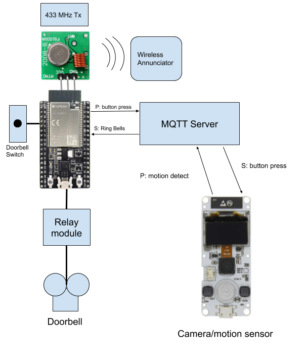
I bought a 433 MHz doorbell that I knew someone else had controlled from an Arduino (I’d normally give credit, but I lost the reference). I didn’t want potential network failures to keep the regular doorbell from working, so I decided to always trigger a relay and send the wireless doorbell code, while informing a messaging server of the events. This MVP is great because it improves my doorbell situation while providing lots of room for growth, such as triggering future security cameras, sending messages etc.

433 MHz Doorbells

433Mhz RF Decoder Transmitter With Receiver Module Kit For ARM MCU Wireless  Geek - US$2.99

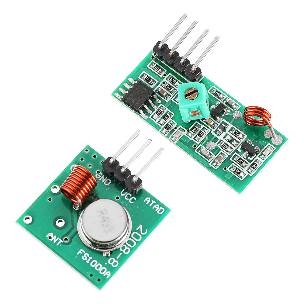
There are some very cheap 433 MHz transmitter/receiver pairs (<$5) that are compatible with a lot of the wireless doorbells. I ended up using the RC-Switch library (available from the library manager). It’s also supported by the RadioHead library.

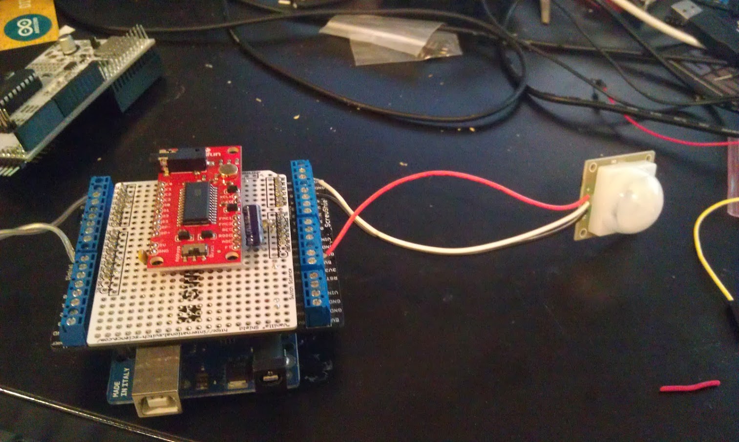
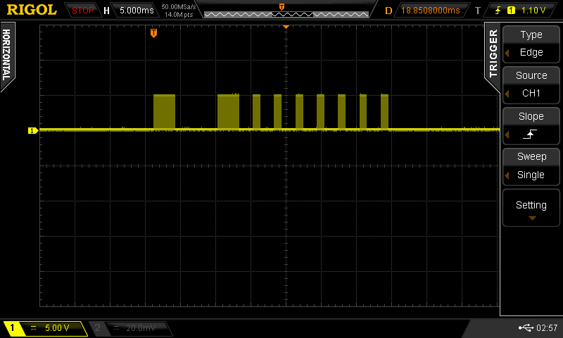
You only need the receiver to decode the transmission from the doorbell’s pushbutton. I just hooked it up to an Arduino Uno and ran one of the receive example sketches. You might get several different “packets’ with different codes, but one of them is the right one. Hook up the transmitter, and transmit the codes one at a time until one of them works.

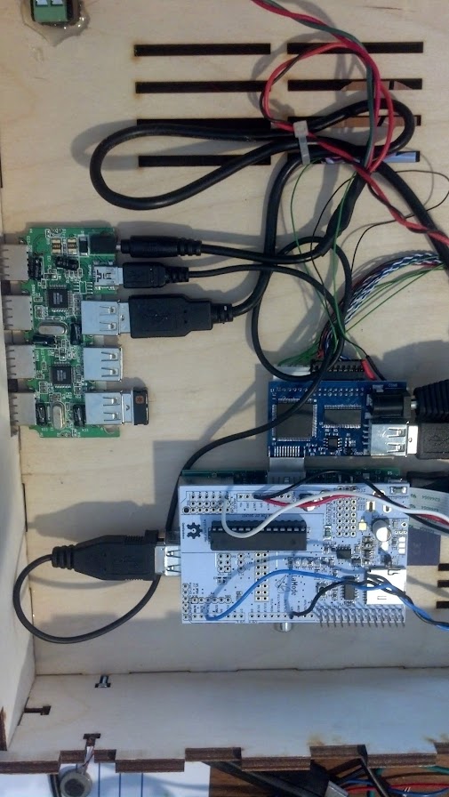
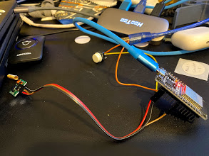
Here you see a rough prototype with a switch standing in for the doorbell button.

Next post we’ll pretty it up, and show some code!

Arduino Robot Class preview

I’m teaching an Arduino Robot class June 29 from 6-8pm at YouDoitElectronics in Needham, Ma. The cost is $99 and you get to take home the robot you build. I’ll show you how to use an Arduino to control DC motors, and read sensors to react to the environment. The robot we’re building will have a sonar sensor for distance, and two line detectors for following a line.
To register email your name phone number and number of participants to events@youdoitelectronics.com. Please include Arduino Robot Workshop in the subject line. You will receive a call back within 1-2 business days. Fee is required at time of registration prior to the start of the workshop. Once registration and payment are complete a reservation confirmation number will secure your spot.

Arduino Workshop and Arduino Resources page

youdoit-arduino class

Had a full house at an Intro to Arduino Workshop at YouDoIt Electronics in Needham last night. Getting ready for this prompted me to start up an Arduino Resources page and update my Intro to Arduino Presentation (which, unfortunately I didn’t get to use due to technical difficulties…)

YouDoIt Electronics is a terrific local resource, carrying tons of Sparkfun and Adafruit products (as well as tons of mechanical and electrical parts, educational toys, AV equipment, you name it!) Thanks Melissa and John for sponsoring me!

Interactive Wall at the Duxbury Free Library

I was Maker in Residence at the Duxbury Free Library in August, where I worked with Teens and some adults to create an Interactive wall for display at the Library.

I met Teen Librarian Ellen Snoeyenobs at the first Make a Makerspace conference at the Artisan’s asylum several years ago, and we’ve been collaborating on bringing more maker activities to her library over the last 2 years. She has an excellent blog reflecting on their successes, failures, and tips : http://librarymakerspace.blogspot.com/

She has her own excellent video here:

Lessons learned

  • Something for everyone. There are art activities for those who won’t go near tech stuff, and plenty of wiring and coding for the techies. Girls, boys, adults alike found something to do.
  • Drawing on skills learned in the past helps to get things done. We did one session on Arduino at the beginning, but in the end, those who already had Arduino experience ending up contributing most in that area.
  • Include a variety of activities. Kids who liked 3D printing and design did various bits to glue on, and use, including a spider that goes up and down. The 3Doodler was used a lot to add decorative elements, as well as enhance some of the 3D prints. And of course, Arduino brought it all to life.
  • Think Off the Wall. Ellen was originally inspired by an interactive wall she saw at MIT. The library, however, wasn’t too keen to be hacking into their existing walls. Ellen came up with the idea of a portable partition, and I helped select one (made of poly-carbonate) that we could drill. It had the additional advantage of being semi transparent, so we could mount our fireflies (addressable LEDs,) behind the wall.
  • Surprise learning. There were all sorts of bonus learnings, including how to scale a drawing up using a grid!

Technology

  • The library had previously received a grant that enabled them to buy a bunch of Spark Fun Inventors kits. We used velcro to attach the Redboards and their attached breadboards to the back of the wall.
  • We used a PIR motion sensor to trigger the bird moving, and cheap Chinese HC-SR04 ultrasound distance sensor to light up the peacock’s tail as you waked closer.
  • WS-2812 LED strips provided bling for both the peacock’s tail and the fireflies.
  • Birdsong was provided by a Sparkfun MP3 Shield
  • Movement was done with micro servos, and one continuous rotation servo from parallax.
  • The shifty eyed fox was implemented by a great design from Dampboot on Thingiverse

Come see it!

Our Grand Reveal of the Arduino Interactive Garden Wall will take place on
Thursday, September 10th at 4 p.m. on the Upper Level of the Duxbury Free Library.

We’re hoping some of the Teens as well as adults who had a hand in making it will talk about the experience.

From Blink to Bot: Introduction

JoebotJoe McDermot (leader of the Boston Robotics Meetup) discovered many members of the Boston Robotics Meetup had never scratch built a robot, so he sourced some cheap components from China and led a group build session. Joe did a fantastic job, keeping the price to $60, for a robot with 4 motors, Arduino clone controller,  3 ping sensors and IR control. (Joe’s a modest guy, but I call it Joebot)

After building it, a lot of the members had trouble with the programming, trouble I’ve seen when people attempt to do slightly more complex projects on the Arduino, after doing the basic Blink, and other examples.

In this series of posts, I will attempt to show how to coordinate several activities in an Arduino program. While the robot is an excellent challenge, the lessons here can be applied to any project where you have to “simultaneously” read sensors, control actuators, etc.

Bot-BOM:

  • 4 DC gear motors with Wheels
  • Acrylic base
  • L9110s  BLUE motor control board (2 channel, 2 wire control per motor)
  • IR receiver
  • 2 – Ping type distance sensors
  • Arduino Nano V3 Clone
  • Breadboards, wires, etc.

One note of caution here, many of the Nano clones used counterfeit FTDI chips, and were bricked by the new windows driver. DCCDuino, is actually not an out and out copy and uses a different USB-Serial chip, and works well.

JoeBotLabledNext post we’ll work out how to handle motor control.


NovaBooth – Improving the Open Source Photobooth

NoVa SnapAs you may have read here previously, we (the Wyolum Gang) created a photobooth for the Open Hardware Summit, for the purpose of customizing the e-paper badges we made for the conference attendees. This processed the pictures into a small black and white image for the e-paper badge, and saved it onto the badge’s micro-sd card.

I was headed to help out at the Northern Virginia Maker Faire, and thought it would be fun to update the photobooth to take full color pictures, upload them to the Internet and offer to email them to friends and relatives.

The email message and logo files are easy to add and customize.

For basic construction, visit the original post, but download the new software here:

github: https://github.com/wyolum/NovaBooth

The fabricate directory has the laser cut files, arduino for the AlaMode Program, and scripts for the python photobooth code.

Edit custom.py to customize the email subject and message. config.py contains the authentication information for the google email and posting accounts. You’ll need to set up application specific passwords for this on your google account. You can use the same account, or separate.

Wireless keyboard, had to add a powered hub.

Problems

  • External powered hub was a pain.
  • Proto-screw shield was too heavy and lifted off
  • Some of the nuts came loose in travel.

Photobooth 1.5

To solve the first problem, I determined to replace the non-powered hub in the photobooth with a powered one.  I tried to add power to the unpowered hub, and this worked at first, but then took out the power supply and made the raspberry pi flakey too.

Scratch that, I ended up using a small belkin powered hub. I y-connected the power to it.
I noticed that  a convenient orientation put  4 ports right next to the edge,  so I cut a hole in the box to expose them.

Luckily AlaModes ship without shield headers installed, so I replaced the AlaMode and protoshield with an AlaMode that was directly soldered to the button, led-strip, power and ground.

I updated the AlaMode’s photobooth program directly from the photobooth. Apparently the new AlaMode’s pullups weren’t as strong, so I added a 5.7k pullup to the Button Pin.


Instant Party for Arduino Day!

[youtube]http://youtu.be/65PD9Plcd30[/youtube]You Do It Electronics in Needham asked me to help out with their Arduino Day celebration on Saturday March 29, and I wanted to make a nice Arduino demo that uses parts that they sell, relatively simple, and Fun! You Do It also sells DJ and disco equipment, so I thought what would be better than Arduino controlled Disco lights and Music?

Here are the Parts I chose:
Sparkfun Motion sensor (to trigger the Instant Party)
Sparkfun MP3 Shield
Arduino
Sparkfun proto-screw Shield (to make it easy to hook up.)
Power Switch Tail – turn on the disco lights

You’ll also need a micro-sd card and some music. I chose some Creative Commons Techno from Soundcloud:

https://soundcloud.com/captain-karacho/city-17
https://soundcloud.com/captain-karacho/brainwreck

First, we need to find out what pins are in use in the MP3 Shield so we can figure out where to hook up the motion sensor and power switch tail.
The easiest way to do that is by looking at the schematic, or this page at Sparkfun: https://learn.sparkfun.com/tutorials/mp3-player-shield-hookup/hardware-overview
MP3 Shield hookup

Digital Pins 5 and 10, and Analog Pins A0-5 are all free.

I used the analog lines because they are close to the power and ground pins for both the power switch tail and the PIR motion sensor.

Because the PIR output is open collector, I use the internal pullups on the Arduino.

Git the code here: https://github.com/osbock/InstantParty


Electrify Your Halloween! Making it Move!

In late September, I  led a workshop at the Duxbury Free library on making interactive Halloween displays, and more recently I set my project up on our porch for Halloween.  One of the most effective ways to make your front porch scary and immersive is to pay attention to sound, and to make things move.

The first part (making it scream) was documented in this post. This is about the movement part, creating a pop-up inflatable ghost, completely from scratch. It was very successful and popular!with the kids. Unfortunately I didn’t get any video, but I can cover the construction.

I like inflatables, and wanted to try making my own. One thing that made this really easy was a really cool product called Powerswitch Tail. This allows you to control an AC outlet from a digital signal. Its available from Adafruit and Makershed. It’s essentially a short extension cord with an opto-isolated relay in line. This eliminates any dangerous AC wiring with relays, and protects your Arduino and other circuits as well.

Next I needed to make the Ghost. I use white kitchen trashbags at home, and I took three of them, two laid end to end (with the end of one cut off.) I cut the third bag in in thirds and used the outside sections for arms. I used simple transparent packing tape to bond the edges.


A total of 3 bags (top and bottom, both arms)

I used one of those small vortex fans, and taped it around the output side.


Boo! Attached to the fan, and inflated.

Hook the powerswitch tail to a digital IO on an Arduino and you are good to go. As I mentioned in the last post, you can get the code on github here.


Lazertag hacking

My friend Nick asked if we could find a way to create enhancements to the fantastic, but no longer made Lazertag Team Ops system.

Many people believe that this was the Pinnacle of consumer lazertag, and I tend to agree. In addition to working better both indoors and out, it could host games where it kept track of the scores of multiple players.

Nick and his friend Max came over and we were totally successful! Here’s a brief video showing our results.

[youtube]http://youtu.be/x3LsPc1kz2I[/youtube]

First we looked up what was known about the protocol. I found this:

http://web.archive.org/web/20090304155723/http://lasertagparts.com/ltto.htm

via the LTTO (LazerTagTeamOps) Yahoo group. As you can see the page is no longer in service, but the archive still has it.

Here’s the cool diagram that they created in the past, apparently based on Aaron Nabil’s reverse engineering effort:

From the Internet Archive’s record of http://www.lasertagparts.com/images/ltto_signals.gif

Of course it’s easy to say this now, but the protocol was pretty easy to decode by looking at the output on a scope. The only difficulty I had was capturing just the shot, as the dome is constantly shooting out messages saying what team, etc.

Here’s an example of a shot that is created by our program:

Lazertag shot

you can see that it uses a 38 kHz carrier (to distinguish it from random IR noise. Fortunately Ken Shirriff wrote a terrific IR Remote library for the Arduino. It’s not really well documented, but there is a sendRaw() function that we used to send the actual timings for the shot. Grab his library here. The library uses preset pin numbers for the LED output, but you can change them in the library itself, you just need to use one of the PWM pins as he uses the timer function to create the carrier frequency.

[code]

unsigned int shootOne[] = {3000,6000,3000,2000,1000,2000,1000,2000,1000,2000,1000,2000,1000,2000,1000,2000,1000};

// the one confusing thing with the irsend.sendRaw command is that the last argument is labled hz, but it’s really
// kiloherz. The lazertag team ops uses the common 38kHz frequency.
irsend.sendRaw(shootOne,sizeof(shootOne)/sizeof(int),38);

[/code]

For the TV-B-Gone, I modified the original firmware to send out the appropriate pulses, similar to my previous hack for camera remotes. The V1 firmware uses uncompressed codes, so that is what I started with.

Grab the example code zip here, and let me know on google+ if you build anything with it!

Also if you want to use Git to pull the code (whether or not you want to fork) it’s all checked in to the baldwisdom github repo:

https://github.com/osbock/Baldwisdom