Category Archives: FamilyFun

Holiday Ornament Design Challenge

Over the Holiday break, I challenged my family to design some ornaments for our tree. So far, only Mason (17 year old son) rose to the challenge, and I think he did very well indeed.

He did the designs in OpenSCAD, and at first hardcoded all the measurements until I encouraged him to make the designs fully parametric. This piece was designed to accept a light (from the string lights on the tree) in the bottom. Printed in Natural PLA with about 15% fill, giving it a kindof stripey, plaid texture.

This was printed without support on the Ultimaker 3. The very inside top is a little stringy, but hardly noticeable, and very easy to clean up.

The second design was really the first one he did, and isn’t fully parametric. You’ll have to scale it in your slicer, but it turned out pretty nice.

I printed it in white, thinking it might be fun to use a sharpie to color in the facets. This was printed with the PVA support.
I also printed it in transparent ColorFabb XT. I had a problem with the wipe tower, so the top was a bit messed up with mixed PVA and XT, which broke off, but a light fit into it, and I think it looks nice.

I encourage you to sit down and design with your family this holiday. You can get the sources for these at: http://github.com/osbock/HolidayOrnaments. Feel free to do some Pull requests to add your own designs!

For younger, or less mathematically inclined designers, I recommend Tinkercad.com, or I’m sure there are cool Ipad apps out there. Let me know if you have a favorite!

First Video, and a few Quadcopter lessons learned

I had a lot of fun flying the 3DR Solo in the last couple of weeks, but after a while you just want to DO something. Until I develop my “copilot” add on board to activate some cool add ons and sensors, photography is the obvious thing, and my bundle even came with the stabilization gimbal. I was planning on buying a “fauxpro” from MCM electronics but found out the gimbal is really “locked” in to Genuine GoPro ™. I could probably hack it, but the biggest advantage of using a real GoPro is the expansion connector on the back allows you to start and stop video, take pics etc. from the remote. So I gritted my teeth and plunked down $250 at Costco.com on a GoPro Hero4 bundle that included an extra battery and SD card.

Here’s my first flight video:

I’m very pleased with the video (shot at 1080p and 60 fps) though obviously, my control and shot planning skills need some work.

Shortly after this, I crashed and trashed 4 propellers (ouch$). I was running it on “cable cam” where you fly to different positions, record them and then you can run the quadcopter between those positions like it was on a cable. When I ran it to the end of the “Cable” it ended up being about 5 feet higher than when it started, got tangled in some wires, and crashed upside down. It sat there and ground the propellers to dust, as I didn’t know how to turn off the motors until it detected the crash (maybe a minute later).

Lesson Learned: Don’t expect GPS to get you exactly to a spot (it’s only good +- 3 meters at best) and don’t fly in a confined airspace unless you are really good and manually controlling it!

Other Lesson Learned: RTFM, except there was no FM! Well, online there is, and a quick web search revealed holding down a and b buttons together will cause an emergency motor stop.

Arduino Robot Class preview

I’m teaching an Arduino Robot class June 29 from 6-8pm at YouDoitElectronics in Needham, Ma. The cost is $99 and you get to take home the robot you build. I’ll show you how to use an Arduino to control DC motors, and read sensors to react to the environment. The robot we’re building will have a sonar sensor for distance, and two line detectors for following a line.
To register email your name phone number and number of participants to events@youdoitelectronics.com. Please include Arduino Robot Workshop in the subject line. You will receive a call back within 1-2 business days. Fee is required at time of registration prior to the start of the workshop. Once registration and payment are complete a reservation confirmation number will secure your spot.

DIY Rayguns!

IMG_20160117_244535475

I’ve been going to Arisia (one of Boston’s Science Fiction Conventions) for several years. I always have a great time, and it always amazes me the amount of volunteer effort that goes in to providing amazing programming for everyone. This year I wanted to give something back so I came up with the idea of people building rayguns.

(NOTE: My extra kits are available in my etsy shop: https://www.etsy.com/listing/265475569/diy-raygun-kit)

Regular LED strip is super cheap when you order it from China. It normally runs off 12V, but a 9V battery lights it up just fine. I created a simple laser cut frame to put some LED strips, and then some cool laser cut acrylic disks to give it that groovy 50’s raygun look.

I bought most of the parts myself, but special thanks goes to my friend Jeremy Green at Charles River Maker for donating Laser time for cutting the kits. He’s your goto guy for design, prototyping and digital to physical services with laser cutting and lots of 3D printers!

IMG_20160124_200031275

A switch makes the trigger, and there’s a fin with holes to add decorations.

IMG_20160124_202035981

First cut a strip of LEDs. Mine consisted of groupe of 3 led sections.. Cut a strip of 5 sections, two sections on each side and one straddling the middle:

IMG_20160124_200123002

next glue on the handle “dimensional” bits. These are mainly to make a recess for the battery, and maybe wrap the handle. Super glue works pretty quick, but you could probably use wood glue or whatever is appropriate for your frame:

IMG_20160124_200915995_HDR

Glue the trigger button on, (kindof low, as the disks are pretty close. Actually I moved it down abit after I put the disks on (later step)

IMG_20160124_201644540_HDR

Line up the battery clip and shorten the leads to connect one end (I chose the red, positive wire) to the positive contact on the LED strip. A small wire went from the negative contact to the switch and the other lead of the switch to the negative lead of the battery clip.

IMG_20160124_201656322

Test, viola!

Next line up the disks where they fit. back them off and put a drop of superglue where each disks goes in order.

IMG_20160124_202344870

IMG_20160124_202812456

The source files for laser cutting are at: https://github.com/osbock/Baldwisdom/tree/master/DIYRayguns

And now a few pics from the workshop at Arisia!

IMG_20160117_244513394_HDR

IMG_20160117_244050950_HDR

IMG_20160117_244531403


Parametric Littlebits Mounting system

TL;DR version: I got to borrow the littlebits synth kit, and created a parametric version of the mounting board. The source files are available on github: https://github.com/osbock/Baldwisdom/tree/master/LittleBitsMounts

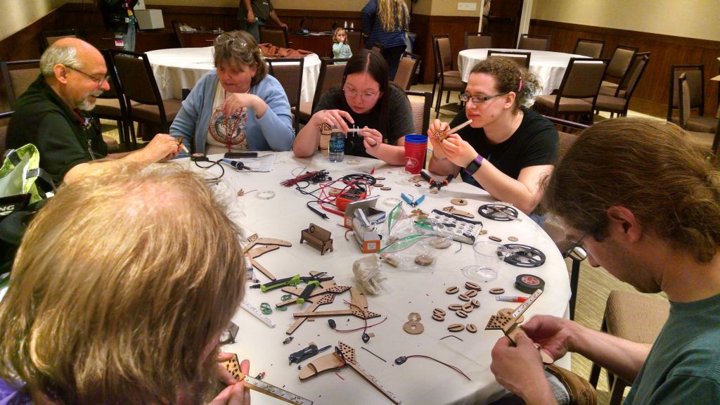
The Newton Free Library applied for and got a cool LSTA ( Federal Library Services and Technology Act) Grant to do a bunch of STEM related programs, and I have the honor of doing a bunch of coding and robotics workshops there over the next few months.

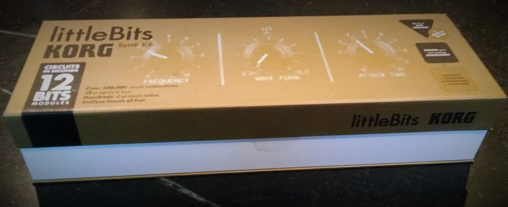
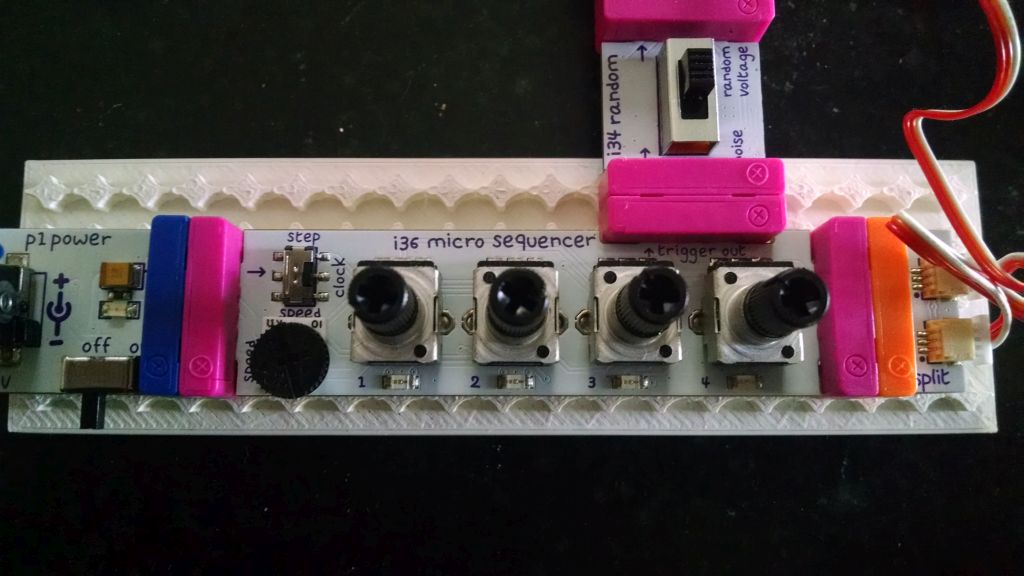
They got a bunch of cool new equipment to run these programs including Finch Robots, Arduinos (Sparkfun Inventors Kits), a KIBO robot, and … wait for it… a bunch of Littlebits sets. NFL Assitant Director Jill Grabowski was kind enough to lend me the coolest littlebits set: The Korg Synth kit.

korgset


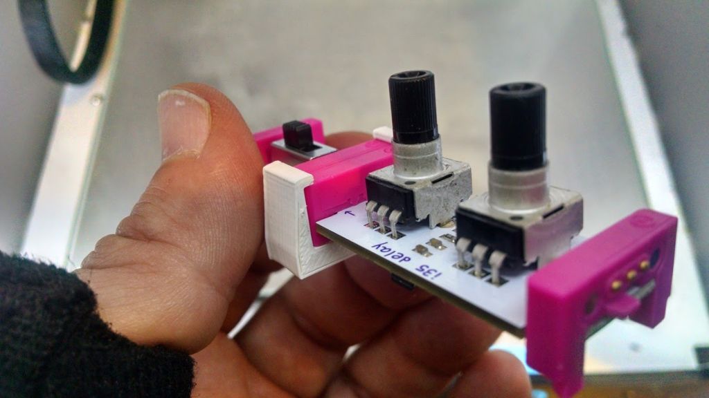
If you aren’t familiar, they are modular electronics blocks that snap together with magnets. Unlike earlier “electronics construction sets” these are pretty foolproof, well thought out modules instead of just individual components. As Founder Ayah Bdeir says ,

AT LITTLEBITS, WE ARE ON A MISSION TO DEMOCRATIZE HARDWARE BY EMPOWERING EVERYONE TO CREATE INVENTIONS, LARGE AND SMALL, WITH OUR PLATFORM OF EASY-TO-USE ELECTRONIC BUILDING BLOCKS.

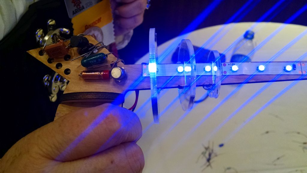
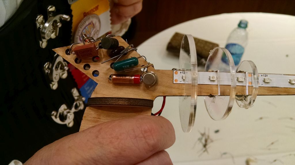
Unfortunately the thing that makes Littlebits easy is also it’s greatest weakness: The magnetic connection system.

Especially when making something you have to manipulate (like a musical instrument), they tend to come apart, you lose power, etc.

Now some of the other (more expensive) sets come with mounting plates (that you can also buy separately. I didn’t have one though, but I do have a laser cutter and a 3D printer. How hard could it be? Well, the devil is in the details.

First I looked to see if it was already done. Thingiverse (I know boo….) has a few designs, including some by littlebits themselves, mostly specific component mounts.

Rex Brodie posted this cool clip that fastens adjacent modules together.
clips

It works pretty well (very solid) but it was difficult to put the two bits in without pulling and pushing and putting a bit of strain on the boards. (Especially scary when the ‘bits are on loan).

I tried just measuring and cutting holes with my laser, or a simple model with Open SCAD but I just couldn’t get the spacing quite right.

Thingiverse user Kris Kitchen had posted this design:
littlebitsgrid

which I printed and actually worked quite well. Only problem was, it was an STL (Surface Tessellation Layer) file, and thus not easily modifiable. I wanted wider, arbitrary shapes, etc!

I could however pull Kris’s design into OpenSCAD, and do a trick to measure the “holes” and spacing.

This little bit of code:
[code]
projection(cut=false)difference(){
translate([0,0,-41])import(“LittlbitsGridthin.stl”);
translate([0,0,-10])cube([250,40,10]);
}
[/code]
cuts off the bottom so the holes will show and projects the outline in 2D.

projection

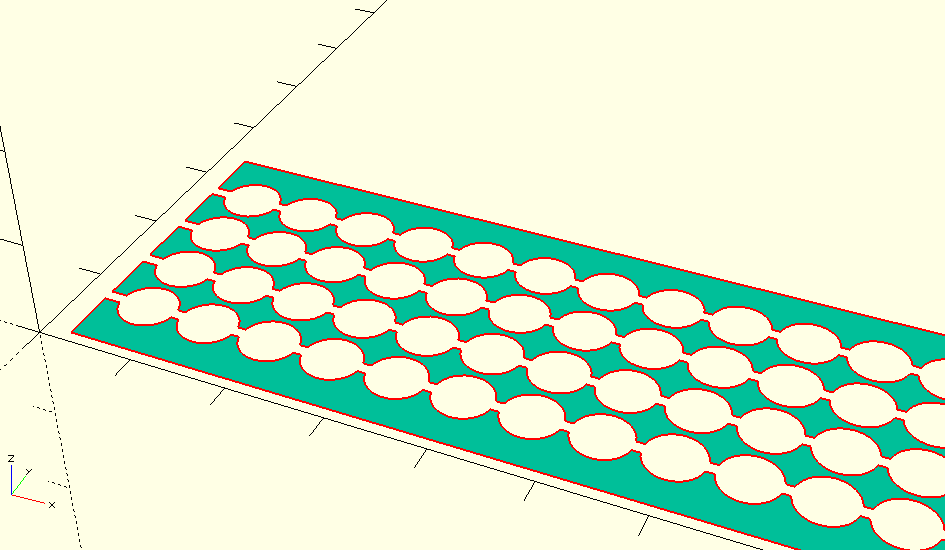
I then exported this as a DXF file, and used inkscape to make measurements.

If I haven’t lost you by now, the part you are waiting for, the measurements (which I couldn’t find anywhere after much googling!)

  • Holes: 6 mm diameter
  • Spacing (edge to edge or center to center): 6.63mm
  • spacing is also 10.5% of hole
  • 1.294mm knockout line

The percentage bit is important (I calculated it, 6.63/6) if you are designing in inkscape because that is how you do a grid of evenly spaced objects.

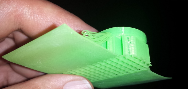
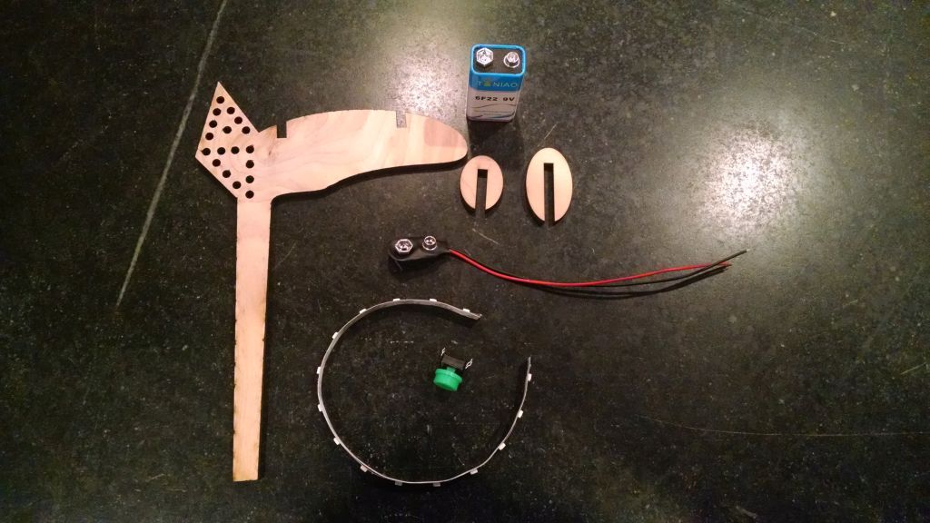
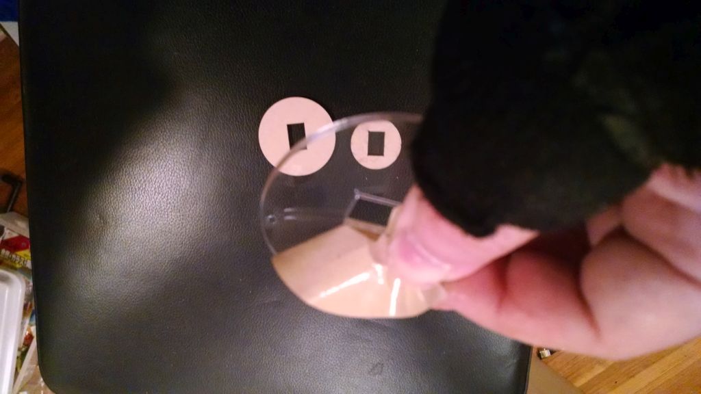
I made a couple of attempts at a laser cut version, but it was very brittle, and I didn’t take into account the laser’s kerf (width of cut)

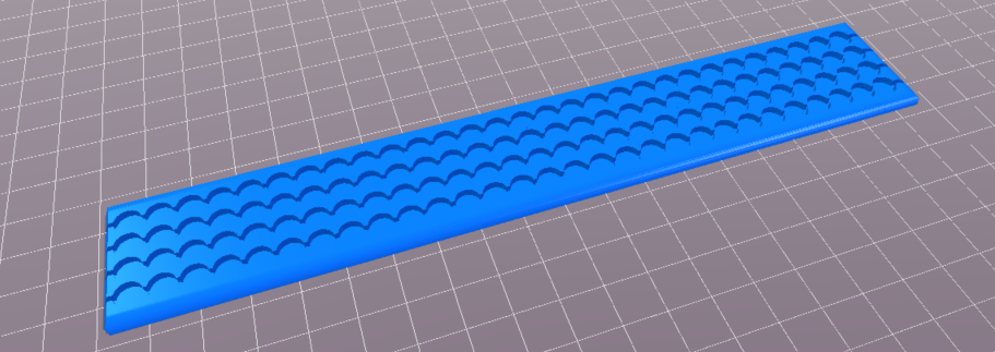
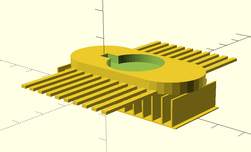
The 3D printed version came out pretty well, but the holes were a bit too small, so I enlarged them by .2mm (.1mm on the radius). and it worked perfectly!
littlebitsmounted

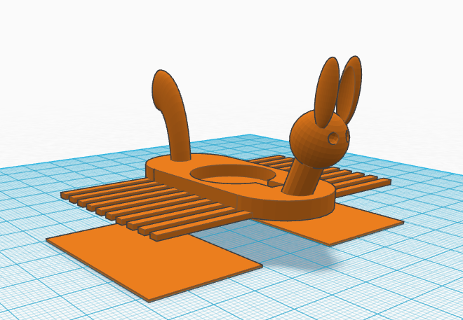
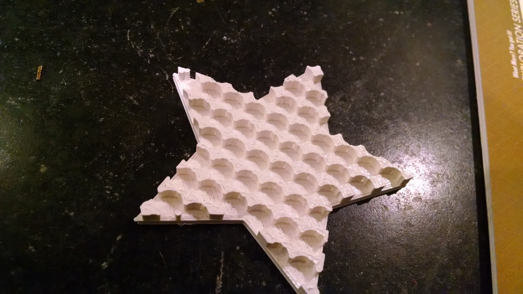
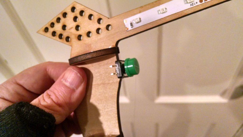
Now we can make mounting boards in any shape!
star

The source files are available on github: https://github.com/osbock/Baldwisdom/tree/master/LittleBitsMounts

MacGuyver Copter Part 3: Success!

If you have been following along, in Part 1 and Part 2, I was trying to build a simple, cheap and easy quadcopter from spare parts. Well, the simplest methods failed, time to get out the laser!. Acrylic isn’t the best material for a quadcopter frame. It’s relatively heavy, and fairly brittle. but it’s  easy to cut in a laser cutter, which I happen to have, courtesy of Wyolum.com.

20150721_215248

Did it work? Well, it didn’t flip over, but started spinning a bit in place.  When I picked it up with the props going, some of the air was blowing up! I somehow got the ordering and placement of the motors wrong. I cracked open my original X5C (wow, that’s a lot of screws!)

I fixed the wiring, and then it flew! About 6 inches off the ground! I noticed that the props were rotating about 1/4 of a rotation over the body which means a lot of backwash, but the main problem is revealed when I weighed it.

The original Syma x5C with camera and battery weighsin at 97 g.

Version L1 of the MacGuyver Copter: 122g. Flew about 6 inches above the ground.

I created a new version with more or less rounded rectangle arms, and a circular central platform. I was worried because acrylic is rather brittle, and I wanted it to be strong.

20150722_174826-001

Version L2 of the MacGuyver copter weighed in at  106g. Flew relatively well, but inertia was killer on flips(lots of altitude loss), and battery runs down very quickly. After about 5 minutes, it was again hovering at 6 inches.

Although we think of plastic as light, acrylic is fairly heavy so I tried some plywood. All I had on hand was some 1/4 inch cheapo birch plywood from home depot.

20150722_180330


I forgot to record the wieght of this one (I think it was between 100 and 110 grams), but it worked quite well. The only problems were that my cutouts came a little close to the edge, and between the cheap plywood (voids) and those thin areas, one of the arms broke in a crash.

The final design simplified the cutout to be a triangle and weighs in at 84g, compared to the x5, without the camera or battery door at 88G. There are probably lighter, equally stiff materials, but this is pretty easy to do.

1-MacGuyverV3

Flys fantastic, at least to my feel It seems better than the stock version without the camera. Even though it’s less “aerodynamic, I think it handles better in a light breeze than the original, probably due to less surface area.

Here’s a (pretty bad) video of it’s flight. Trust me, it’s fun!

I also cut a frame out of 1/8 inch acrylic, but it was way too bendy, and wouldn’t take off. I think the props tended to thrust up, and bend it toward the middle, and the IMU (Inertial Management unit) couldn’t figure out a way to get enough power out to get it in the air.


MacGuyver Copter Part 2: Total Ghetto, Total Fail

Spoiler alert: in part 3, we finally succeed!

If you read the first post  you know that I was inspired by all the cheap replacement parts for the Syma X5. Also the motor mounts have all sorts of interesting attachment points, including a tube that fits a 3mm (who knew they were a standard size?) bamboo barbeque skewer. I’ve seen people bodge together quadcopters with “real” controllers but with crappy wooden frames, so I thought why not.

First I cut some skewers so the props were centered where they were in the original Syma X5. They were 9 inches center to center.

20150715_174605

I taped it all together, with the controller in the middle. I didn’t have much hope, as  you can see the fit on the motor mounts isn’t tight, and I was afraid they would twist. I taped them the best I could but as you can see in the video it was a total fail.20150715_223808

One problem I noticed, was that I had mounted the controller board upside down. Doh! The purpose of the controller is to keep it upright!

20150716_115519

Next I designed a 3D printed hub for the middle, secured with hot glue. I found some tiny screws (scavanged from many tear aparts!) and drove those through holes in the arms and through the bamboo skewers. This time it worked better but spun. I concluded that the bamboo was twisting with the motor torque. Probably true, but later I also discovered that I had the motors mounted in the wrong place.

Conclusions: I need a sturdier frame, but still need to keep the weight light (how light, well, I find out in part 3…)

Droobots: 3D printed Bristlebots

3D printing Bristlebots gives you lots of creative options, and here’s a new way to create the bristles, or legs of the bots. More details follows the video, and the source code is at: https://github.com/osbock/droobots

Mark Peeters, came up with a clever idea for making lacy  fibrous flowers with a 3D printer, by taking advantage of FDM’s greatest weakness: the need to support overhanging structures.

drooloop-group1 kopieTurning them over in my hand, I had the insight that they could be perfect bristles! I fired up OpenSCAD and started designing a simple bot:

The trick is that you have to let them droop down, so you have to have something in the center to hold it up, and have the legs be unsupported. I designed in support material for the body.

droobot-scad

It’s tricky if you make the support walls to thin, the slicer may ignore them. Too thick and it’s harder to remove. This version works fairly well, but is a little too heavy for my taste.


I use Cura, and I was thinking about how to use it’s native support which is very thin and easy to remove. There is an option for printing support material only when there is an overhang  on the baseplate. I put thin (.4mm) rectangles under the legs, but not under the body:

droobot-needs-support
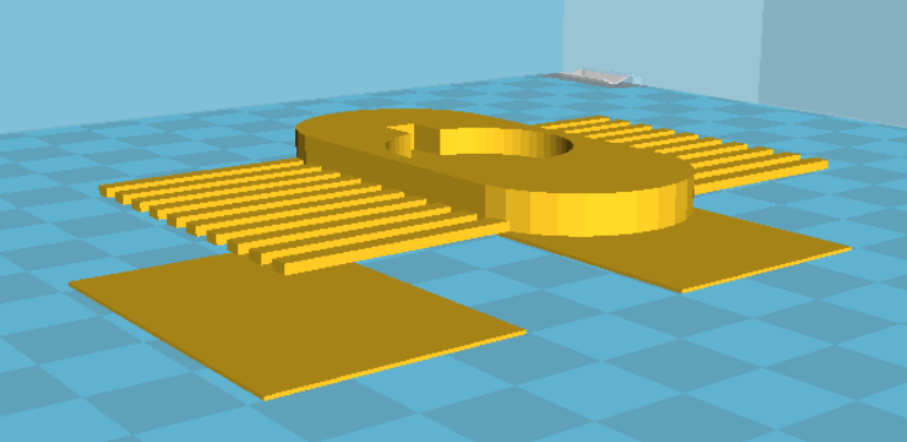
This works out quite nicely, and gives a speedier print.

cura-suportThe other thing that’s helpful is to turn off the fan during the leg creation. You can either use the “Tweak at Z” plugin, if you use Cura, or edit the Gcode.  I located the layer where the legs started and  inserted an M107 (stop fan) command, and then when it was on a layer above, add M106 S255 (fan full on)

After printing, I use a hot air gun to soften the legs to press them down more to a right angle. This give a more energetic movement than the splayed legs right off the printer.

You can also experiment with trimming them with scissors.

Last but not least, I imported the basic STL into tinkercad, and added a head and tail for a little more pizzazz!

tinkered-droobpt


Nano quads: is the Cheerson CX10A a good way to learn?

Continuing the quadcopter obsession, It’s hard not to run across the myriad of nano and mini quadcopters out there. They are cute, and offer the opportunity to fly indoors. My neighbor who flies a DJI Phantom 3 Pro said he learned on the Cheerson CX10. I ordered the upgraded version (CX10A) from BangGood in China, and while I was waiting, I saw them in action at Einsteins workshop in Burlington, MA at a robotics meetup. It looked really fun and their local quadcopter enthusiast made it look easy to fly, however other folks had a bit of difficulty.

Note, you can also buy it from Amazon for only a couple of dollars more and have it in two days!

Well, it arrived, and it certainly is cute!
Cheerson_in_hand

Battery Power

Being tiny (though not the smallest…) It has a very small battery, and it’s inside the case soldered to the board. While the sites advertise replacement batteries, it’s not an easy swap. You’s have to cut the connector off the new battery (Be careful!) and solder it to the board. It comes with a little USB plug charger that charges it in about 30 min. My flight times were initially longer, but now I get about 5-6 minutes without prop guards.

Prop Guards

Now, I was still a newbie (though I had some practice flying the Syma X5C) and I broke a lot of props (order plenty of spares!)
It doesn’t come with prop guards so I 3d printed some from designs on thingiverse, and later ordered an aftermarket propguard that was much lighter.

Aftermarket on the Left, 3D printed on the right

How does it fly?

Let me say this: It’s all about the thrust, and I’m afraid the tiny props just don’t provide a lot. Without propguards it flies reasonably well, though it’s not going to win any awards for turning quickly.  With the prop guards, it has significantly more inertia, and no more thrust, so it tends to be a bit more jerky. It falls faster, stops slower, and in general is hard to fly. Not a great thing for a beginner learning to fly. Also keep in mind, this thing is tiny, and you can easily loose track of it.

It also has an acrobatics mode, if you push down on the right joystick, and then push it in the direction you want it to flip, it will execute a nice flip for you. Don’t do this too near the ground (or other people…) as it’s likely to lose some altitude in recovering from the flip.

Range limitations (and a fix)

When I got better at flying it, and was taking it outside, I thought it was broken. It would stop turning in one direction, or just suddenly I’d lose control. I noticed that up close, I didn’t have these problems, but 20 feet away, yuck.

I’d seen some youtubes where people extracted the little wire antenna on other quadcopters and their controllers, so I cracked open the controller, drilled a little hole in the case and fed the wire antenna through, and now it behaves great! I can fly it at least a block away. Don’t bother cracking the copter itself open to do the same thing, as there is no wire antenna, it’s just built into the PCB.

CX10controllermod

Headless Mode

The CX10A differs from the original CX10 in that it has a “headless mode.” Normally when you fly a copter away from you (back of the craft toward you) Left is Left and Right is Right. If the copter is flying toward you, it’s reversed. If you push the stick left, the quad will go right, and vice versa. In more advanced quadcopters, a special “headless” mode is implemented with an electronic compass, that allows whatever direction you take off in to be the “normal” direction. now, no matter which way you fly, the quad will go Left when you push left, and Right when you push right. On the CX10A, they try to do this by keeping track of turning (it does have a gyroscope sensor) in software. It works….For a while, until it gets confused, and then you have to turn the copter off, and re-pair with the controller. Also, any bump or crash, makes it either go crazy (one or two motors on full speed) or just stop responding all together.

Conclusion

It’s a fun toy, and once you learn to hover relatively well, it’ fun to fly it from one person’s palm to the next. It’s a bit flakey when it crashes,  and is underpowered, so I really wouldn’t recommend it for learning to fly. A larger copter, (even a mini, like the Hubsan X4 or the Eachine H8 which I’ll review next) are more agile flyers. I don’t have any other Nano-copters to compare it with, but the bigger ones are easier to fly in general. The nano size can be more readily flown indoors (with even my poor flying ability!) but you should watch out for crashing and you are going to have to clean things like hairs out of the props it if lands in an untidy corner.