Joe McDermot (leader of the Boston Robotics Meetup) discovered many members of the Boston Robotics Meetup had never scratch built a robot, so he sourced some cheap components from China and led a group build session. Joe did a fantastic job, keeping the price to $60, for a robot with 4 motors, Arduino clone controller, 3 ping sensors and IR control. (Joe’s a modest guy, but I call it Joebot)
After building it, a lot of the members had trouble with the programming, trouble I’ve seen when people attempt to do slightly more complex projects on the Arduino, after doing the basic Blink, and other examples.
In this series of posts, I will attempt to show how to coordinate several activities in an Arduino program. While the robot is an excellent challenge, the lessons here can be applied to any project where you have to “simultaneously” read sensors, control actuators, etc.
Bot-BOM:
4 DC gear motors with Wheels
Acrylic base
L9110s BLUE motor control board (2 channel, 2 wire control per motor)
IR receiver
2 – Ping type distance sensors
Arduino Nano V3 Clone
Breadboards, wires, etc.
One note of caution here, many of the Nano clones used counterfeit FTDI chips, and were bricked by the new windows driver. DCCDuino, is actually not an out and out copy and uses a different USB-Serial chip, and works well.
Next post we’ll work out how to handle motor control.
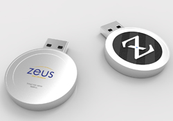
Sparkfun launched a free cloud data service for your devices. It’s limited (rolling last 50MB) but also open source so if you want to roll your own you can do as much as you want!
This is an example of how doing a service and open source can benefit you. As they say
Our hope is that you buy a SparkFun widget to connect your next beehive.
It looks easy to use, and besides making it easy to put your own sensor data up, data from all other users is public, making it available to data scientists and hobbyists.
I’m looking forward to trying it out, and if I do I’ll share here!
As you may have read here previously, we (the Wyolum Gang) created a photobooth for the Open Hardware Summit, for the purpose of customizing the e-paper badges we made for the conference attendees. This processed the pictures into a small black and white image for the e-paper badge, and saved it onto the badge’s micro-sd card.
I was headed to help out at the Northern Virginia Maker Faire, and thought it would be fun to update the photobooth to take full color pictures, upload them to the Internet and offer to email them to friends and relatives.
The email message and logo files are easy to add and customize.
For basic construction, visit the original post, but download the new software here:
The fabricate directory has the laser cut files, arduino for the AlaMode Program, and scripts for the python photobooth code.
Edit custom.py to customize the email subject and message. config.py contains the authentication information for the google email and posting accounts. You’ll need to set up application specific passwords for this on your google account. You can use the same account, or separate.
Wireless keyboard, had to add a powered hub.
Problems
External powered hub was a pain.
Proto-screw shield was too heavy and lifted off
Some of the nuts came loose in travel.
Photobooth 1.5
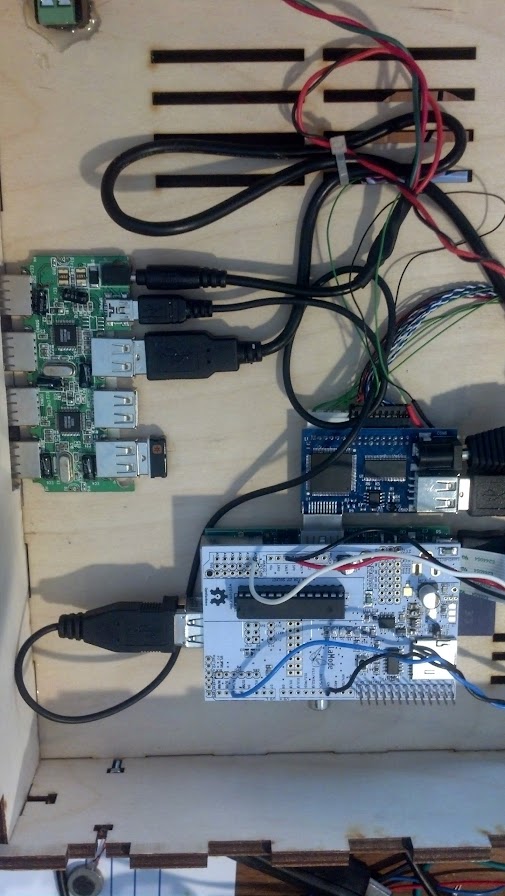
To solve the first problem, I determined to replace the non-powered hub in the photobooth with a powered one. I tried to add power to the unpowered hub, and this worked at first, but then took out the power supply and made the raspberry pi flakey too.
Scratch that, I ended up using a small belkin powered hub. I y-connected the power to it.
I noticed that a convenient orientation put 4 ports right next to the edge, so I cut a hole in the box to expose them.
Luckily AlaModes ship without shield headers installed, so I replaced the AlaMode and protoshield with an AlaMode that was directly soldered to the button, led-strip, power and ground.
I updated the AlaMode’s photobooth program directly from the photobooth. Apparently the new AlaMode’s pullups weren’t as strong, so I added a 5.7k pullup to the Button Pin.
[youtube]http://youtu.be/65PD9Plcd30[/youtube]You Do It Electronics in Needham asked me to help out with their Arduino Day celebration on Saturday March 29, and I wanted to make a nice Arduino demo that uses parts that they sell, relatively simple, and Fun! You Do It also sells DJ and disco equipment, so I thought what would be better than Arduino controlled Disco lights and Music?
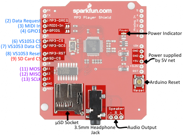
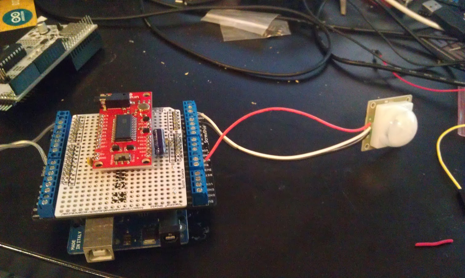
First, we need to find out what pins are in use in the MP3 Shield so we can figure out where to hook up the motion sensor and power switch tail.
The easiest way to do that is by looking at the schematic, or this page at Sparkfun: https://learn.sparkfun.com/tutorials/mp3-player-shield-hookup/hardware-overview
Digital Pins 5 and 10, and Analog Pins A0-5 are all free.
I used the analog lines because they are close to the power and ground pins for both the power switch tail and the PIR motion sensor.
Because the PIR output is open collector, I use the internal pullups on the Arduino.
I attended a meetup of HackBoston, run by Abby Fichtner (HackerChick) from the Harvard Innovation lab. Project 11’s Reed Sturtevant wanted to learn more about Cryptocurrency, so he started experimenting and shared the basics with us at the meetup.
Most people have heard of BitCoin, but Reed shared that it’s so hard to mine now, it’s very difficult to experiment without putting in real money. He found DogeCoin as a fun, and lighthearted alternative. Often used as a +1 or like tipping system for blogs and on social networks.
Pre-work was to set up wallets before the meeting, as they take time (about 5 hours) to synch with the network.
We each recieved 2000 dogecoin at the beginning of the meetup. Then we learned the basics of how to use addresses (essentially the destination of coin transfers. We transferred money to each other.
While doing this Reed went over the basics of cryptocurrency, which I won’t cover here, but the wikipedia article covers it pretty well.
We also created accounts at tipdoge.info which lets you send DOGE via twitter. (feel free to tip @osbock)!
Intro to Mining
If you read the wikipedia article, you know that transactions are verified by a cloud of contributers performing cryptographic checks distributed across the Internet. “Miners” are rewarded both through the creation of new “coin” (which slows) and the distribution of transaction fees. Without special hardware, your chance of winning a race to solve the puzzle that is a cryptocurrency transaction is minimal, so mining pools were created to distribute the work and the reward.
We created accounts on the mining pool site dogehouse.org, created workers (essentially addresses within the pool for your mining processes to communicate) and downloaded and configured mining software.
I recently got a nice “gaming” laptop from Lenovo, because it offered very good price performance, plus it has an Nvidia graphics card which I wanted for computer vision experiments.
Because Nvidia graphics cards contain many parallel processing cores, and Nvidia has released an API that allows their use for general purpose parallel computing, they are often employed for mining.
The Experiment
Following instructions from dogehouse.org, I set up cudaminer (cuda is what Nvidia calls their processing cores) and another instance running the pooling cpu-miner to take advantage of the native cpu cores of my laptop’s i7.
Each mining process (cudaminer and pooling-cpu-miner) were configured to report to a “worker” setup at dogehouse.org.
I then mined overnight to determine:
The kH/s (thousand’s of hash per second) capability of my laptop
How much doge/hour I could mine
Electricity cost of running the computer. (determined with a P3 Kill-a-watt)
Using an exchange rate, I converted into dollars to see if I could mine more doge than the electricity cost.
The Results
The cuda miner was reporting an average of around 80 kH/s and the cpu-miner around 54 kH/s
In 14.07 hours I mined 261.229 Doge for 18.57 Doge/hour, or $.0147/hour (at an exchange rate of .00079$/Doge.) Power usage was approximately 1.4 kWh, which I calculated to cost $.19.
Projecting out to a month, at 134 kH/s, I’d earn a whopping $.95 (and lose a lot of the computing bandwidth of my laptop!)
I could invest in a fancy graphics card and dedicate a computer, but I imagine it would cost even more electricity. So, I would say overall, a negative return on investment.
This apparently became the case for bitcoin as well, until people developed specialized hardware that gives a high H/s rate at low electricity usage, first using FPGA’s and then specialized ASICS (Application Specific IC’s). Doge uses a different Hash algorithm than Bitcoin, so you can’t use the now ubiquitous ASIC mining equipment optimized for the SHA 256 algorithm. There’s a new ASIC to be released soon that supports Doge’s (and litecoin, and others) Scrypt algorithm, and by extending my calculations, the cheapest of these devices ($119) would pay for itself in 3 or 4 months.
I’m going to try to get one to see. Of course, all these calculations are based on assumptions of stability (exchange rate, mining rate etc.) which are completely unreasonable. Still it’s fun to try!
In late September, I led a workshop at the Duxbury Free library on making interactive Halloween displays, and more recently I set my project up on our porch for Halloween. One of the most effective ways to make your front porch scary and immersive is to pay attention to sound, and to make things move.
The first part (making it scream) was documented in this post. This is about the movement part, creating a pop-up inflatable ghost, completely from scratch. It was very successful and popular!with the kids. Unfortunately I didn’t get any video, but I can cover the construction.
I like inflatables, and wanted to try making my own. One thing that made this really easy was a really cool product called Powerswitch Tail. This allows you to control an AC outlet from a digital signal. Its available from Adafruit and Makershed. It’s essentially a short extension cord with an opto-isolated relay in line. This eliminates any dangerous AC wiring with relays, and protects your Arduino and other circuits as well.
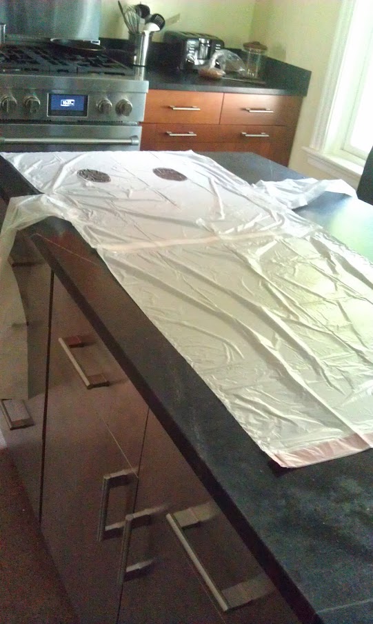
Next I needed to make the Ghost. I use white kitchen trashbags at home, and I took three of them, two laid end to end (with the end of one cut off.) I cut the third bag in in thirds and used the outside sections for arms. I used simple transparent packing tape to bond the edges.
A total of 3 bags (top and bottom, both arms)
I used one of those small vortex fans, and taped it around the output side.
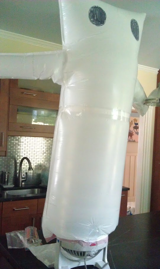
Boo! Attached to the fan, and inflated.
Hook the powerswitch tail to a digital IO on an Arduino and you are good to go. As I mentioned in the last post, you can get the code on github here.
As you know, my Wyolum buddies and I partnered up with SeeedStudios to make a really cool e-paper badge for the Open Hardware Summit which took place last week. We wanted some cool ways for people to customize their badges. Justin created a great simple program for converting images (wifit.py) and I leveraged that software to create a photobooth.
Photo by Addie Wagenknect
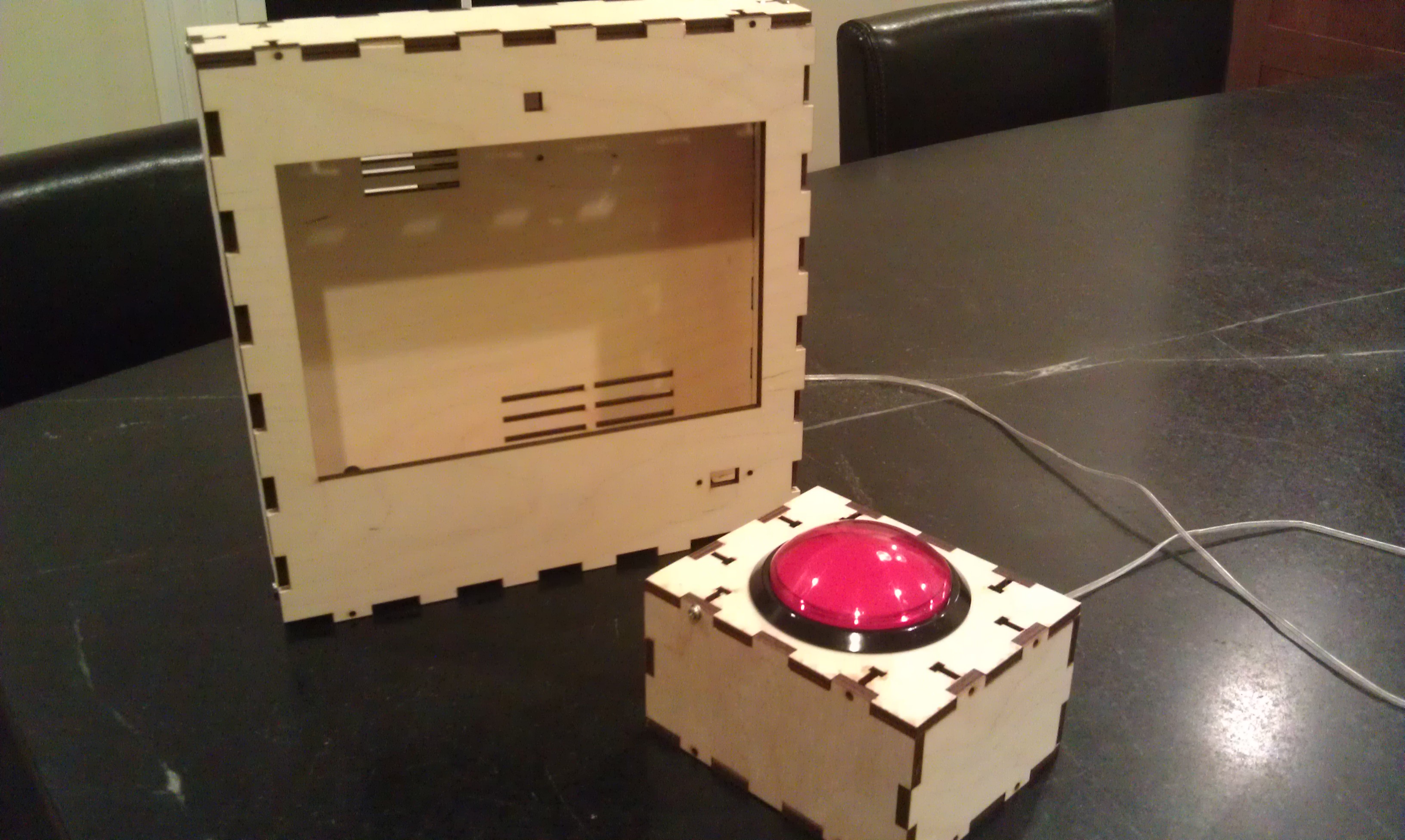
My friend Michael Castor at Makershed built a cool tablet from the Raspberry Pi, and he told me about the nice 10.1″ LCD display and HDMI adapter he found from Chalk-elec.
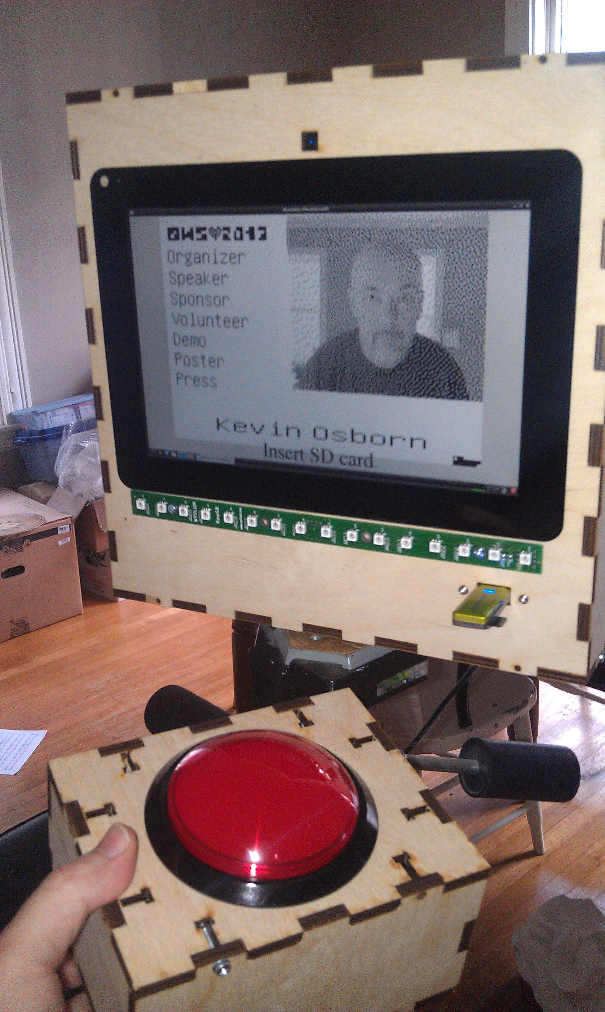
I ordered one, and started figuring out how to put the whole thing together. I also got a big red button from Adafruit. I have been playing with the Raspberry Pi camera and it’s perfect for embedding in a project like this, even though the software is a bit primative at this point (no video for linux drivers, etc.) I used our own AlaMode to read the button and use one of our WS2811 arrays to do a visual countdown before taking the picture.
I’d never really designed anything for laser cutting, and this was my opportunity! I used Inkscape, with the T-slot extension written by Justin. I got the box cut at Einstein’s Workshop (a family oriented makerspace in Burlington, MA.)
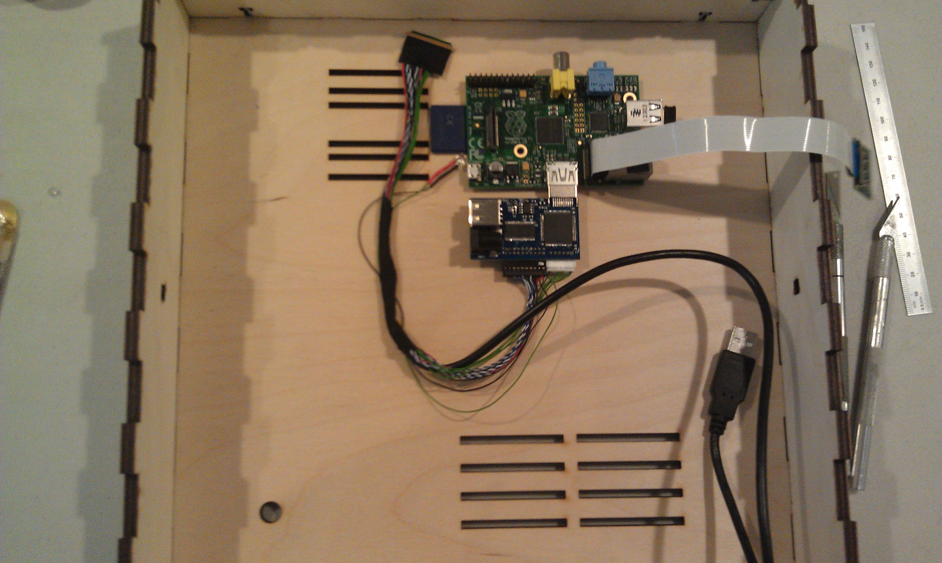
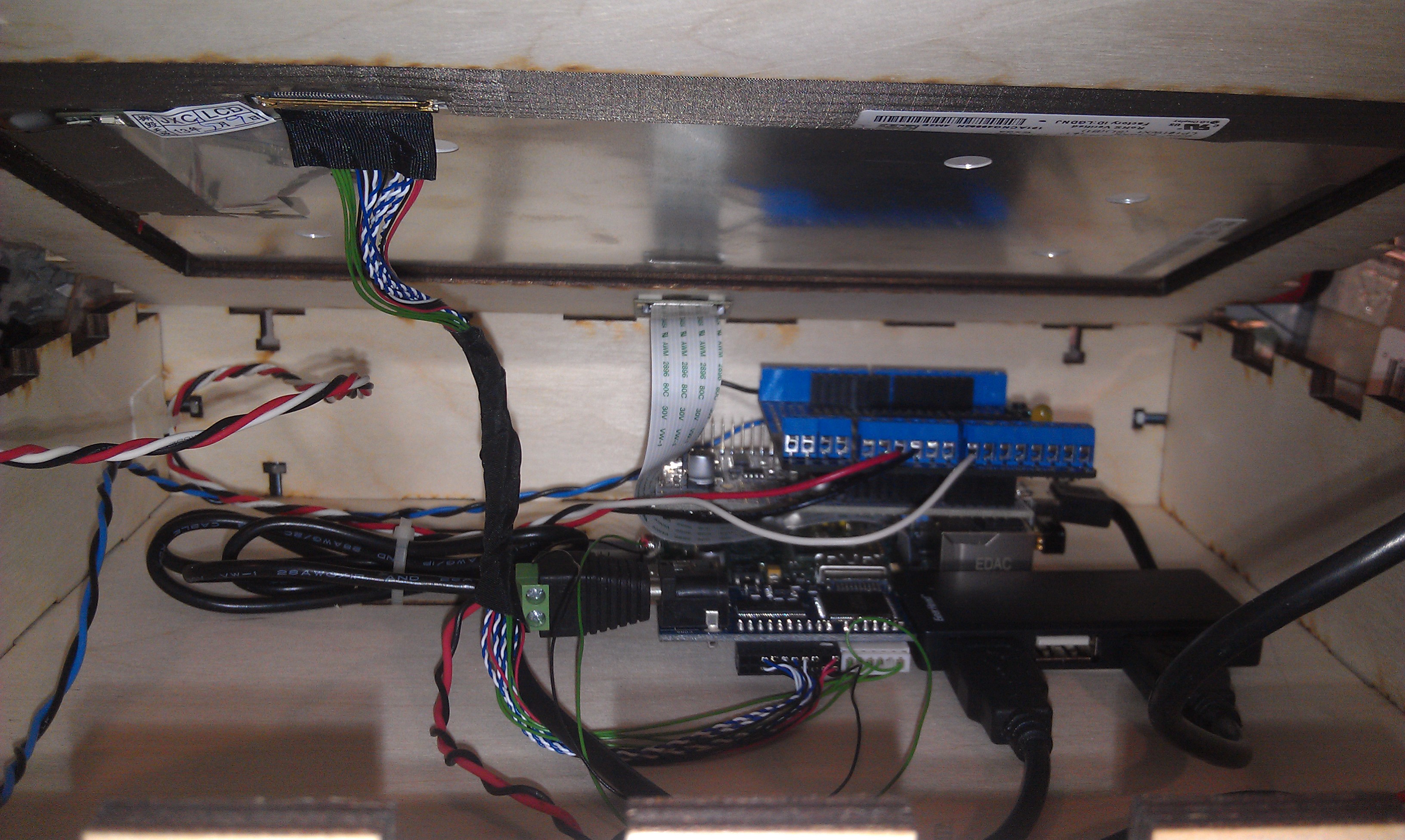
Next, I laid out the components. The trickiest parts were the LVDS cable (though it’s pretty generous) and the Raspberry Pi Camera flex cable.
One really sweet thing about the Chalk-elec hdmi adapter is that you power it, and there’s a USB power port to power the Pi.
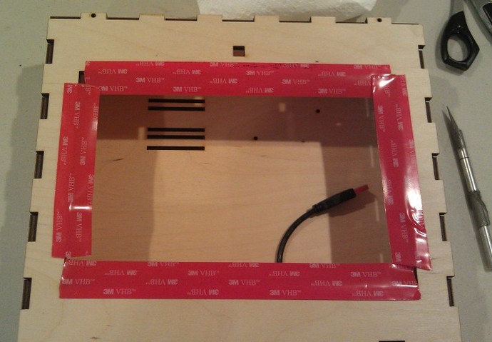
Attaching the LCD to the case is a little nerve wracking, as like most tablet screens, it’s intended to be glued in. I used 3M permanent mounting tape (really not tape but adhesive on a backing roll.) It’s really difficult to cut with scissors (it sticks to everything) I made the mistake of putting it on the bezel and trying to cut it with an X-acto knife. I scratched the paint on the bezel, but I managed to fix it with a sharpie.
The better approach turned out to attach it to the opening, and cut along the opening.
I had to drill a few holes because I hadn’t completely planned ahead, for a jack for the switch box (used a 1/4 phone jack and plug) power, and the 16 pixel LED array.
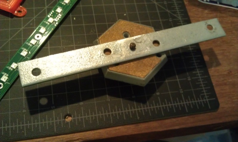
I had planned for it to swivel on the sides from two carriage bolts with wing nuts. This meant making a stand, and I didn’t want it to be just a couple of 2×4’s. Also I was running out of time so I took Justin’s suggestion and made a tripod mount for it. More holes…. And a mending plate from the hardware store. Fortunately I have a set of cheap taps from Harbor Freight, so it was pretty simple to drill the plate and tap it (1/4-20) to accept a tripod mount.
Getting it hooked up with the short cables is a little tricky, but there’s room to get your hands in there:
I
I used a proto-screw shield to make it easier to hook up the button and LED leads. As you can also see, there’s a small usb hub inside too.
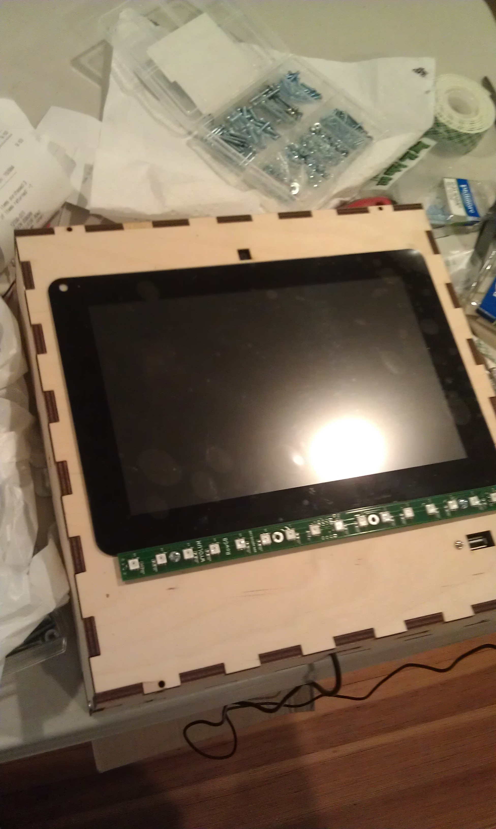
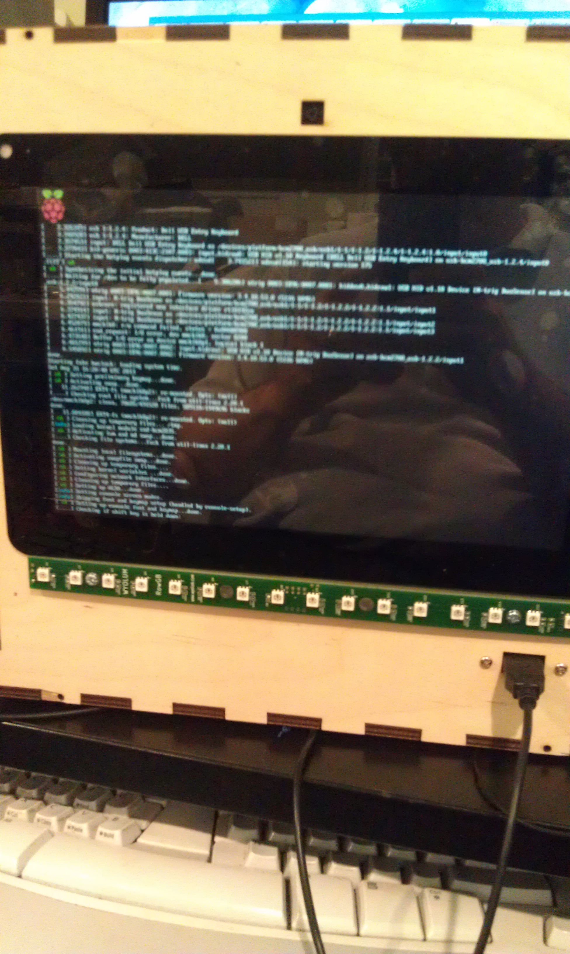
I booted it up:
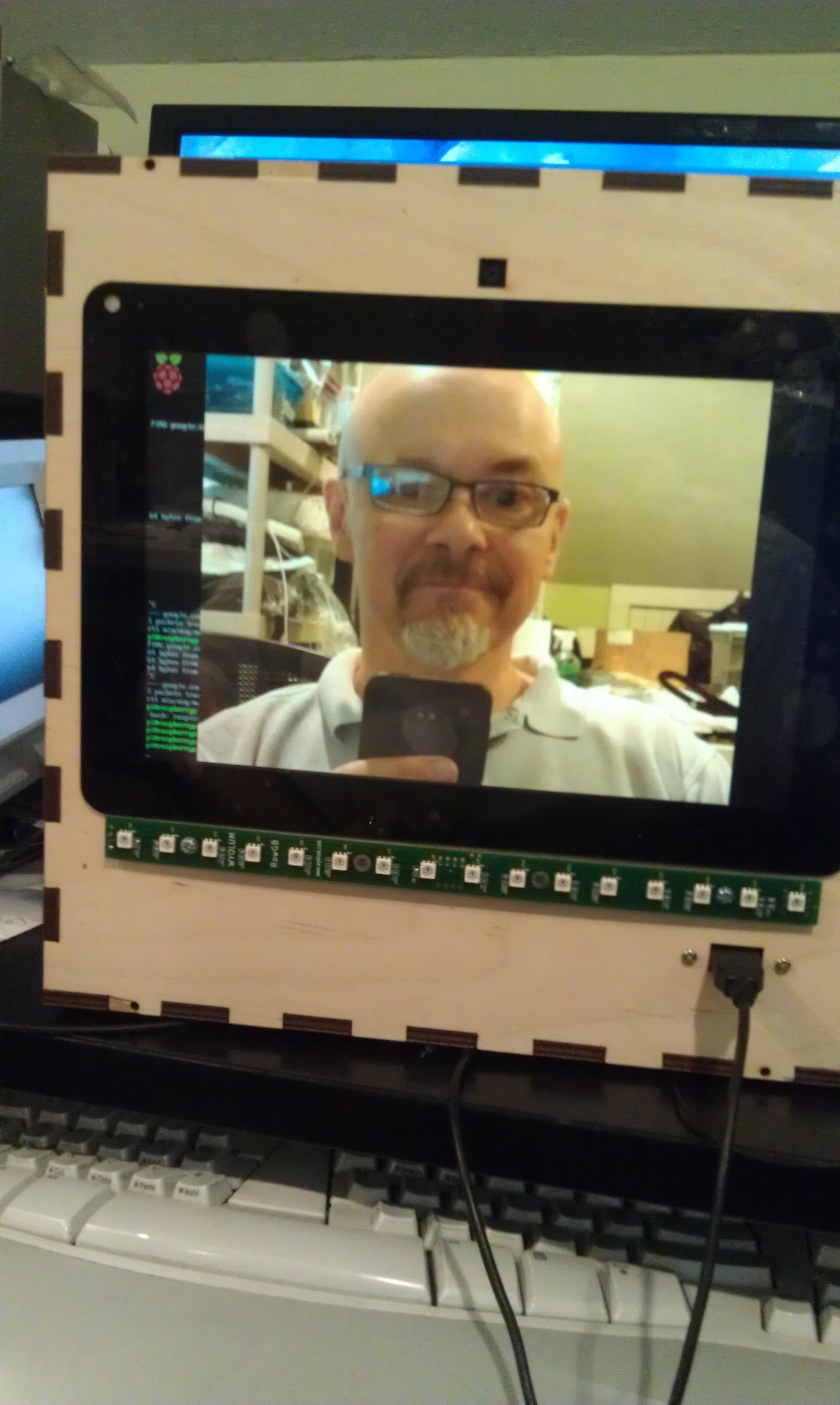
and then hacked Justin’s Wifit program to take a picture:
Justin then created a more kiosk-y gui, and I ironed out a few things with the Arduino code for AlaMode. The gui checks to see if an sd card is mounted, and when it is, it sends an enable command to the button and prints on the screen “Press Button when ready” The AlaMode then monitors for the button, and when pressed, sends the signal to take the picture and begins counting down on the LED strip. You can find the code in our github repository: https://github.com/wyolum/EPD
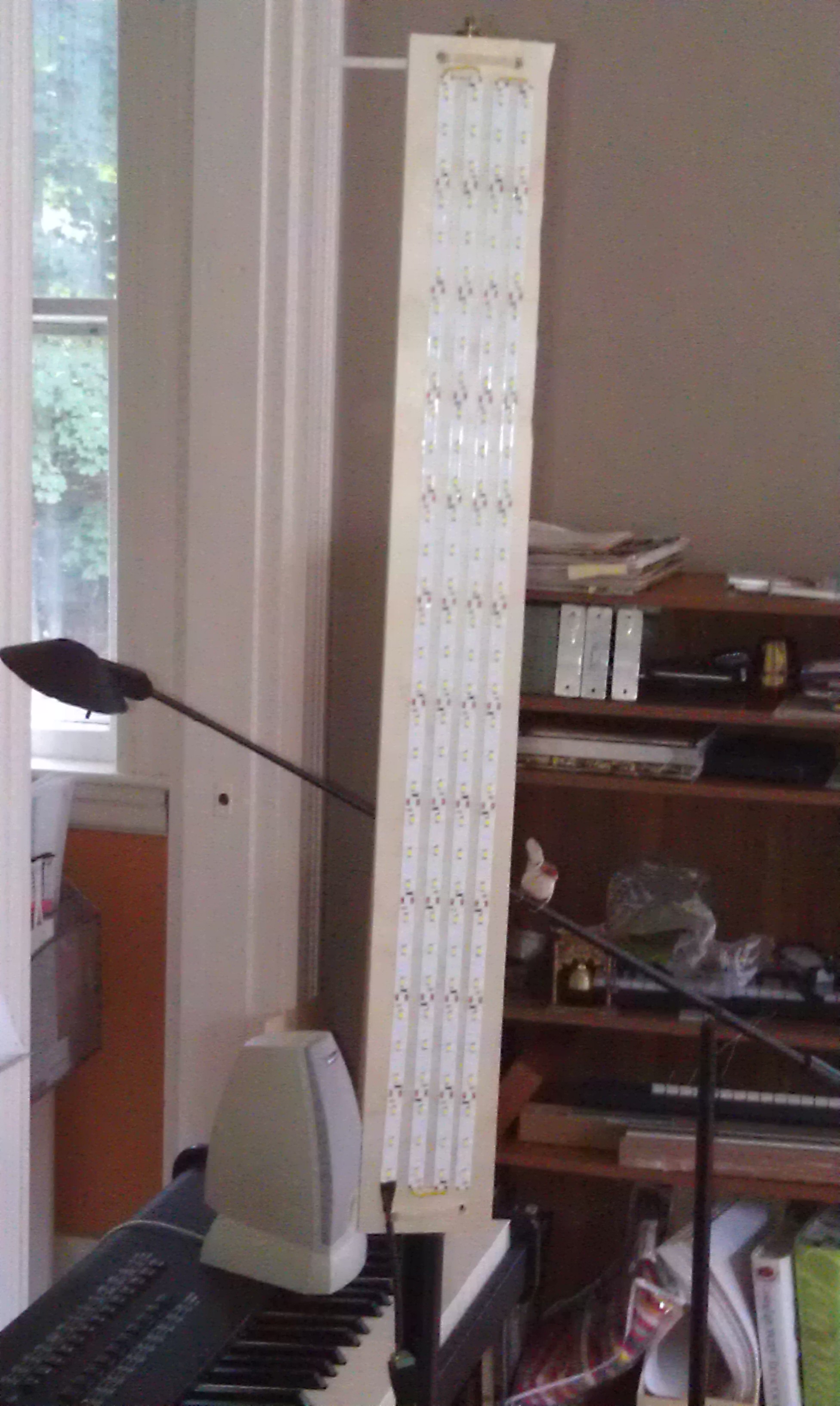
I tried also using the LED strip as a flash, and it worked but made sort of ghastly underlighting like a camp flashlight! So I took some cheap chinese led strip I had around (about $12 for 5 meters) and made a light panel:
And the finished product:
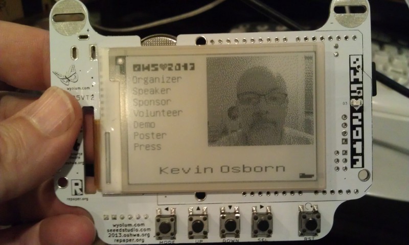
And on the badge:
I’m thinking of modifying the code to upload higher res pics to the Internet with an imprint, or printing them on a portable printer I picked up at a yard sale!
By the way, I left the Raspberry Pi’s wifi dongle attached, as it made it much easier to debug with SSH from my laptop. That said, I did also plug another hub into the one exposed port to use a keyboard and mouse (even though the touch screen does work!) If I had to do it over again, I might bring at least one more port out for other devices.
You’ll notice in the first picture, the Wyolum Logo across the top. Elizabeth Shaw cut that for me and delivered it the morning of the OHS, and it fit perfectly!
My friend Nick asked if we could find a way to create enhancements to the fantastic, but no longer made Lazertag Team Ops system.
Many people believe that this was the Pinnacle of consumer lazertag, and I tend to agree. In addition to working better both indoors and out, it could host games where it kept track of the scores of multiple players.
Nick and his friend Max came over and we were totally successful! Here’s a brief video showing our results.
[youtube]http://youtu.be/x3LsPc1kz2I[/youtube]
First we looked up what was known about the protocol. I found this:
via the LTTO (LazerTagTeamOps) Yahoo group. As you can see the page is no longer in service, but the archive still has it.
Here’s the cool diagram that they created in the past, apparently based on Aaron Nabil’s reverse engineering effort:
From the Internet Archive’s record of http://www.lasertagparts.com/images/ltto_signals.gif
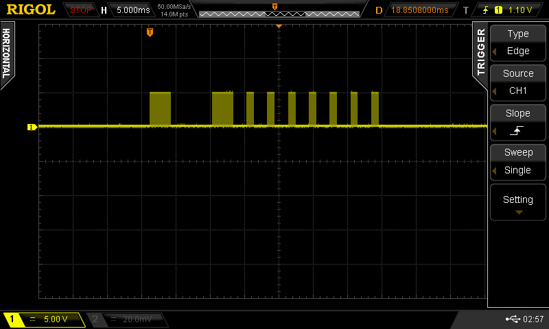
Of course it’s easy to say this now, but the protocol was pretty easy to decode by looking at the output on a scope. The only difficulty I had was capturing just the shot, as the dome is constantly shooting out messages saying what team, etc.
Here’s an example of a shot that is created by our program:
you can see that it uses a 38 kHz carrier (to distinguish it from random IR noise. Fortunately Ken Shirriff wrote a terrific IR Remote library for the Arduino. It’s not really well documented, but there is a sendRaw() function that we used to send the actual timings for the shot. Grab his library here. The library uses preset pin numbers for the LED output, but you can change them in the library itself, you just need to use one of the PWM pins as he uses the timer function to create the carrier frequency.
[code]
unsigned int shootOne[] = {3000,6000,3000,2000,1000,2000,1000,2000,1000,2000,1000,2000,1000,2000,1000,2000,1000};
// the one confusing thing with the irsend.sendRaw command is that the last argument is labled hz, but it’s really
// kiloherz. The lazertag team ops uses the common 38kHz frequency.
irsend.sendRaw(shootOne,sizeof(shootOne)/sizeof(int),38);
[/code]
For the TV-B-Gone, I modified the original firmware to send out the appropriate pulses, similar to my previous hack for camera remotes. The V1 firmware uses uncompressed codes, so that is what I started with.
Grab the example code zip here, and let me know on google+ if you build anything with it!
Also if you want to use Git to pull the code (whether or not you want to fork) it’s all checked in to the baldwisdom github repo:
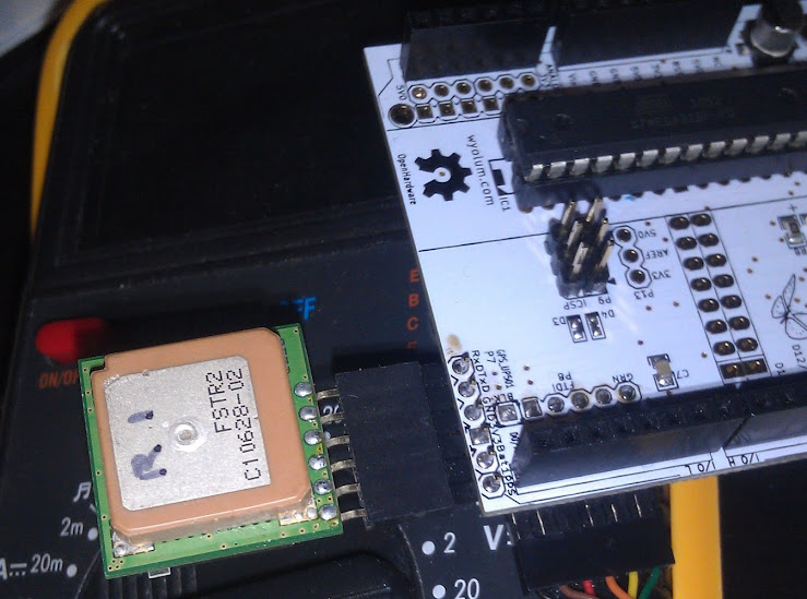
We included a header for the UP501 GPS module on AlaMode.
The UP501 is popular, and has the additional advantage of having a PPS output which can be used to do ultra-precise timing.
Unfortunately we made a little mistake and reversed the silkscreen on the connector (documented in this forum article.) The actual orientation is actually quite logical the RX pin of the GPS lines up with the corner of the AlaMode.
Mikal Hart wrote a wonderful GPS library called TinyGPS
http://arduiniana.org/libraries/tinygps/
The GPS library doesn’t actually talk to the GPS module, but parses the output (NMEA statements) In this case, our example code uses the SoftwareSerial library (also by Mikal Hart!) to listen for the output and feed it to the GPS library.
The pins used in AlaMode are 6 (receive on the Arduino, output from the GPS), and 4 (Transmit on Arduino, input into the GPS module.) Note you shouldn’t actually write to the GPS module from the Arduino, as it’s a 3V module, and the Arduino’s outputs are 5V. It is, however safe to read. SoftwareSerial nss(6, 4);
also in the setup() function initalize the SoftwareSerial for 9600 baud: nss.begin(9600);
After that, you are good to go! Stay tuned, in a future post, we’ll have a guest blogger who will be using the GPS feature of AlaMode to build a compact WarDriving module.
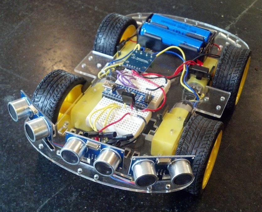 Joe McDermot (leader of the Boston Robotics Meetup) discovered many members of the Boston Robotics Meetup had never scratch built a robot, so he sourced some cheap components from China and led a group build session. Joe did a fantastic job, keeping the price to $60, for a robot with 4 motors, Arduino clone controller, 3 ping sensors and IR control. (Joe’s a modest guy, but I call it Joebot)
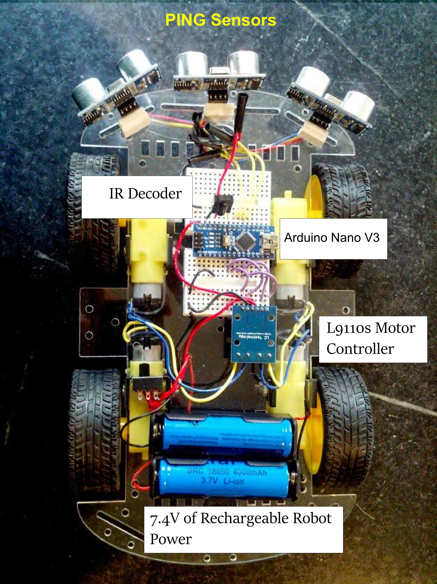 Next post we’ll work out how to handle motor control.