117 people at my 3D printing talk last night!
The Newton Free Library is having 3D printing month and there are programs every week, culminating in public availability of the Library’s new printer.
117 people at my 3D printing talk last night!
The Newton Free Library is having 3D printing month and there are programs every week, culminating in public availability of the Library’s new printer.
I did a couple of EL wire workshops at the Newton Free Library yesterday. It was a great time, and I think everyone left quite happy. Here’s how I prepared, and what we learned during the workshop.
If you aren’t familiar with EL-Wire, or Electro Luminescent Wire, it’s a plastic coated wire that lights up when fed a fairly high voltage (~100V) high frequency AC signal of about 1000hz. (There’s a little more to it, check the wikipedia entry for a nice diagram of the internals…)
I ordered 55 Units that each had 3M of elwire, prewired, and a control unit that runs off of two AA batteries. I got them from an ebay seller (Sure Electronics) in order to get a good price. You can also buy them from domestic sellers like Sparkfun, but they end up being about 2x the cost. It’s good if you can talk to the Seller, as Sure told me that they sold two types, a less expensive one that was dimmer and a more expensive one that is brighter. I’m not entirely sure which one I got! The different colors were definitely different brightness , with Greenish yellow being the brightest, and red/pink being quite dim in roomlight.
I wanted to create an example, so I sewed a segment onto a tie.
A couple of pointers here:
Last, make sure you turn off the lights at the end! We also had a dark closet available to test before we turned off the lights!
Here are some examples of the creations the kids made.
[youtube]http://www.youtube.com/watch?v=PAX8vhzv4dE[/youtube]
A lot of libraries and schools are getting 3D printers, and also, if you personally have one and want to show it off, it’s hard to have people do things in a reasonable amount of time. 3D printers are just inherently slow.
One activity I came up with that allows you to do personalized 3D printing, is to, well, do 2D printing!
We’ll learn how to take some characters, make them into a flat 3D object that can be printed quickly.
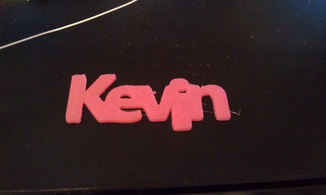
This little logo printed in about 2 minutes on my Printrbot Plus.
We’ll be using inkcape (a vector drawing program) from http://inkscape.org, and OpenSCAD (a 3D drawing language) from http://openscad.org. Download and install (they are both free and open source!)
Here’s a video walk through, but details are also written below.
[youtube]XnpnsKFmvZE[/youtube]
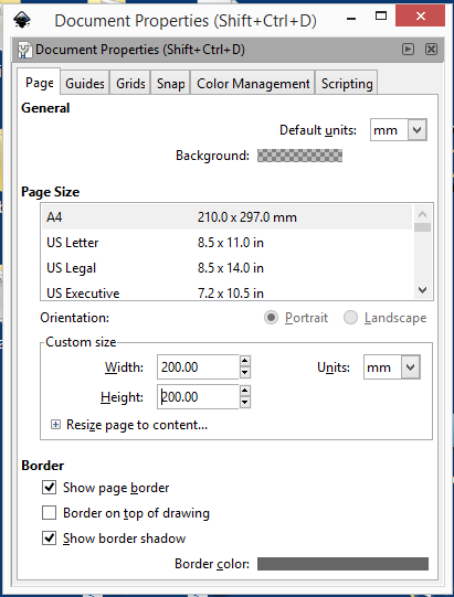
Open a new document in inkcsape. I like to change the document properties to use a real measuring unit, so I can tell how big things are. Change the default units from px to mm, and the size in mm units to your print bed size. In my case 200×200.
Using the Text tool, type your name. I use 72 pt (about an inch or 25.4mm tall) and a font that is fairly blocky. If you want to print larger, you can use more filigreed fonts, but for this exercise, the point is speed, so we need something that will print well small.
Select the name using the arrow tool, and then path/object to path:
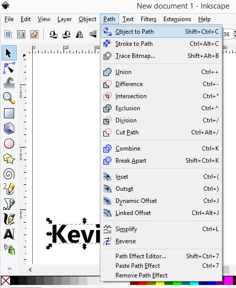
Next click on the second icon down (below the arrow) that is edit path by nodes.
We’re not quite there yet, as we have a path, and we need polygons. Paths include things like splines and other curves. If you grab one of the handles you can see we don’t have straight lines.
It can be a little frustrating working with some of these tools, but there’s a secret OpenSCAD only understands polygons in a DXF file. If you have any splines or arcs, it just ignores them, sometimes giving a warning, sometimes not.
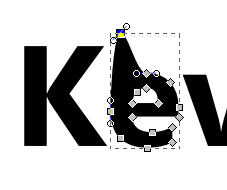
Shift select all of the letters while in path editing mode.
The key to converting any 2D vector drawing is to make sure to select all the segments and click the convert to lines button. Curvy letters like the lower case E in my name will reduce to angular uglies, so , you can add points by clicking the add points button a couple of times.
Next, click on make selected segments lines (make sure all the nodes are selected. If they are grey, they are not selected.)
Next, it’s a little tricky. Click on the second letter in path edit mode, switch to select/move mode (the arrow) and move the letter to touch the first one. Repeat. For the i, I moved it down so the dot was also touching.
At this point we have a bunch of polygons, and OpenSCAD may or may not be able to render it. You can make sure by selecting all the paths, and then perform a Path/Union menu function to simplify the shape.
It’s best to move the whole thing down to 0,0. You can do this with the mouse, or just type in the x,y box.
Next, save it as a DXF file (not the default SVG), in the same directory where you’ll store your openSCAD file.
Then it’s a simple matter of linear_extrude(height=2)import(“kevin.dxf”);
The dxf file has to be in the same directory as the scad file, so you have to save the scad file first before you run it.
It’s probably best to select print quality settings that don’t take too long, but still look ok. You can also influence the print time by extruding at a shorter height, but I think one mm is about the minimum for something you can remove without breaking
In late September, I led a workshop at the Duxbury Free library on making interactive Halloween displays, and more recently I set my project up on our porch for Halloween. One of the most effective ways to make your front porch scary and immersive is to pay attention to sound, and to make things move.
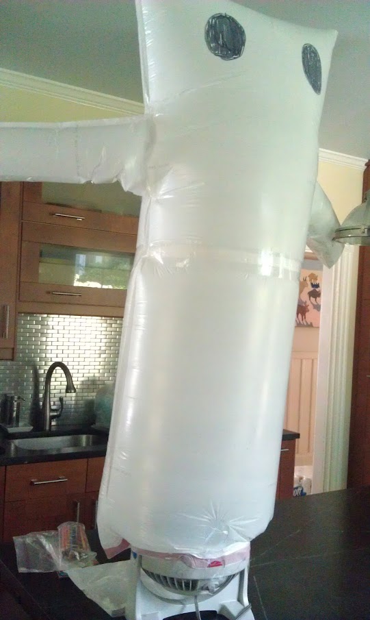
The first part (making it scream) was documented in this post. This is about the movement part, creating a pop-up inflatable ghost, completely from scratch. It was very successful and popular!with the kids. Unfortunately I didn’t get any video, but I can cover the construction.
I like inflatables, and wanted to try making my own. One thing that made this really easy was a really cool product called Powerswitch Tail. This allows you to control an AC outlet from a digital signal. Its available from Adafruit and Makershed. It’s essentially a short extension cord with an opto-isolated relay in line. This eliminates any dangerous AC wiring with relays, and protects your Arduino and other circuits as well.

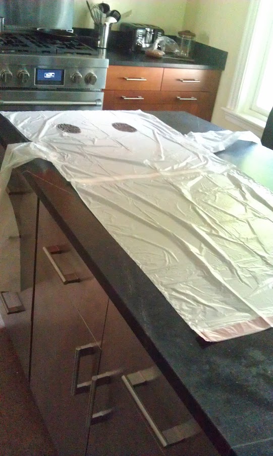
Next I needed to make the Ghost. I use white kitchen trashbags at home, and I took three of them, two laid end to end (with the end of one cut off.) I cut the third bag in in thirds and used the outside sections for arms. I used simple transparent packing tape to bond the edges.
I used one of those small vortex fans, and taped it around the output side.
Hook the powerswitch tail to a digital IO on an Arduino and you are good to go. As I mentioned in the last post, you can get the code on github here.
In late September, I led a workshop at the Duxbury Free library on making interactive Halloween displays, and more recently I set my project up on our porch for Halloween. One of the most effective ways to make your front porch scary and immersive is to pay attention to sound, and to make things move.
In this post, I’ll cover making sound, the next post will cover my moving ghost. There are lots of ways to make sound by control, and in reaction to people coming on to your porch. My original idea was to use a motion sensor, and then trigger an AC relay to turn on a cassette boombox. Because the boombox could have the mechanical play button pressed with the power off, when you turned the power on, it would play.
Then, I ran across the sparkfun voice recorder module at YouDoIt Electronics (my local hacker supply place!)
 There are other ways to make sound (and probably easier) but this was fun, and I’d already spent the money. If I had to do it over, I might use either the Adafruit wav shield, or a new entry, the very cheap Garan MP3 Module from Seeedstudio (I’m probably going to order one of these for next year!)
This breakout is for a chip that was originally meant for a voice recorder with some buttons to trigger the different segments. It’s not very well documented on the sparkfun site, but one of the comments pointed me to http://ianlangelectronic.webeden.co.uk/#/voice-recorder/4562321245. That with the datasheet, let me build a simple Arduino library to control it. You can download it from github here.
First you need to wire it up. Here’s a fritzing diagram showing the connections:
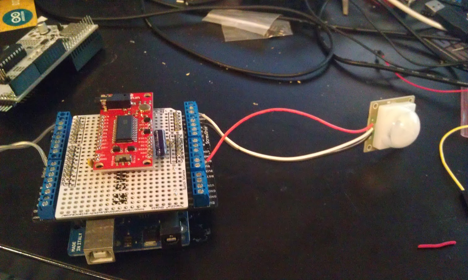
In order to make it more reliable, I mounted it on a protoshield. I also like using a proto-screw-shield to hook up the external components.
In this case, the motion sensor (https://www.sparkfun.com/products/8630) on the right, and the wire going off to the left connects to a powerswitch tail to control a fan for the ghost.
I used PC speakers connected directly to the jack on the sparkfun voice module.
A little about the PIR motion sensor. The data sheet says it operates at 12V, but sparkfun says it operates from 5-12V. I have a Parallax module that is a bit easier to use, but I couldn’t find it and once again YouDoIt rescued me with the sparkfun part. A few other things to note. Since it is open collector, you need a pullup on the input. I used internal pullups in my Arduino code. When I tried to run the system off of one of those USB battery packs, it was unreliable and had very short range. Using an AC adapter worked fine, but if I had to do it over, I might use a motion sensor designed for 5V. The other thing was that the wire colors were confusing. Ground was White, Signal was Black, and VCC was the only one that had a “normal” color of red. (GND is usually black.)
You can find the code on github here. You can control it via the serial port by entering a message number (0-8) and then ‘r’ or ‘p’ for record or play. It uses the onboard microphone for recording.
I chose to use the button on the protoscrew shield as an arming button, but you can also control that through the serial port. ‘m’ toggles whether or not motion activates the sound and PowerSwitch tail output.
Here’s the complete code (at the time of this post) remember to install the ISD library first:
[code]
#include <ISD.h>
// delay between motion activations
#define ACTDELAY 10000L
// motion sensor
#define MOTION A4
#define ARMButton A5
// powerswitch tail
#define powerSwitch 7
// LED
#define LEDPin 13
ISD isd = ISD();
void setup() {
Serial.begin(115200);
// motion sensor
pinMode(MOTION, INPUT);
// open collector requires pullup
digitalWrite(MOTION,HIGH);
// powerswitch
pinMode(powerSwitch,OUTPUT);
digitalWrite(powerSwitch,LOW);
pinMode(ARMButton, INPUT_PULLUP);
pinMode(LEDPin,OUTPUT);
Serial.println(“enter a message number to play or record or r/p”);
}
// globals
int msg =0;
boolean motion = false;
boolean soundonmotion = true;
boolean powerswitchonmotion = true;
int lastReading = HIGH;
boolean ARMState = false;
long lastActivation = 0L;
void loop() {
// check arming button
if (digitalRead(ARMButton) == LOW){
ARMState = ARMState?false:true;
// cheap debounce
delay(500);
if (ARMState){
digitalWrite(13,HIGH);
soundonmotion = true;
motion = true;
powerswitchonmotion = true;
Serial.println(“Armed!”);
}
else{
digitalWrite(13,LOW);
motion = soundonmotion = powerswitchonmotion = false;
Serial.println(“Unarmed”);
}
}
//check motion sensor
long currentTime = millis();
if (motion){
int currentReading = digitalRead(MOTION);
if ((currentReading != lastReading) && (currentReading == LOW) && ((currentTime – lastActivation) > ACTDELAY)){
lastActivation = currentTime;
Serial.println(“activating motion”);
// if enabled turn fan on first
if (powerswitchonmotion){
digitalWrite(powerSwitch,HIGH);
delay(1000);
}
if (soundonmotion)
isd.play(4);
if (powerswitchonmotion){
delay(5000);
digitalWrite(powerSwitch,LOW);
}
delay(1000);
}
lastReading = currentReading;
}
if (Serial.available() != 0)
{
char c = Serial.read();
if (c >= ‘0’ && c <=’8′)
{
msg = (int)(c- ‘0’);
Serial.print(“msg selected: “);
Serial.println(msg);
}
else if (c == ‘r’)
{
isd.record(msg);
}
else if (c == ‘p’)
isd.play(msg);
else if (c == ‘m’){
//toggle motion activation
motion = motion?false:true;
Serial.print(“motion is “);
Serial.println(motion);
}
else if (c == ‘f’){
powerswitchonmotion = powerswitchonmotion?false:true;
Serial.print(“powerswitch is “);
Serial.println(powerswitchonmotion);
}
else if( c == ‘s’){
soundonmotion = soundonmotion?false:true;
Serial.print(“sound is “);
Serial.println(soundonmotion);
}
}
}
[/code]
[youtube]http://www.youtube.com/watch?v=JiCylYs6G0o[/youtube]
I’ve been working with a number of area librarians to create maker and STEAM workshops for their libraries. In preparation for some more advanced workshops, I worked with Nina Taylor, the teen librarian at the Morse Institute Library in Natick, Mass. to put on a vibrobot workshop.
The kids were great, and some immediately took to experimenting, decorating and creating wild things, while others needed getting used to the idea of doing something beyond following directions. Almost all of them said they would come back to do more, so I consider it a resounding success.
In addition to making Bristlebots (invented by Evil Mad Scientists) and sold as a kit by Makershed, we also made “drawbots” for which I made vibro-packs from salvaged motors and battery packs.
The Makershed kit is great, in that wires are already attached to the batteries, making assembly very easy.
For the drawbots, we taped markers around a cup as legs and then attached my vibro-packs. You can make any motor vibrate by attaching a weight off center to the shaft.
As you can see in this picture, I made one by taking the propeller off a bubble blower toy, and hot gluing a screw in.
I didn’t love this, and was scratching my head when I thought “doh!, I have a 3D printer!”
I created a very simple model in Open SCAD, that was adaptable to the various salvaged motors..

You can download the source here, or from Thingiverse. You can use the customizer widget on thingiverse, but it’s much faster if you have OpenScad installed and you tweak it yourself!
I’m most proud of the the free fan (ok, I lost the fan part) from a local bank, but it makes a great, all in one battery pack, switch and motor!
It’s a fantastic introduction to making, so try it yourself!

After many hours of tweaking and fiddling, I was finally getting decent prints out of my first generation printrbot plus that I got used from a friend. I learned a lot about filament quality, differences in materials and the importance of bed levelling. I bought and installed a bed leveller upgrade from Printrbot.com, and printed and installed some belt tensioners.
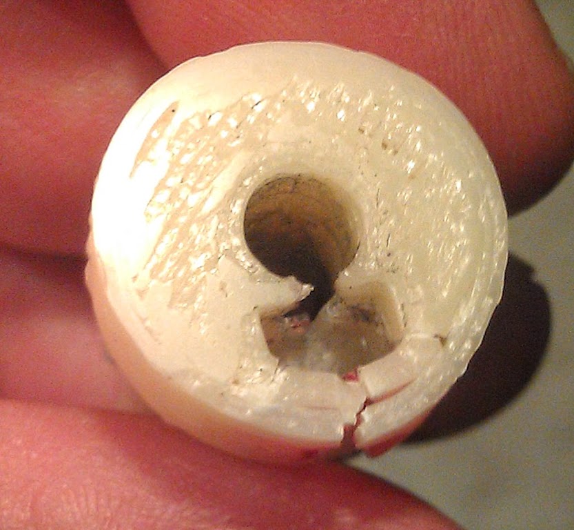
I got a couple of good prints and then pow, every couple of rows would be offset! But my belts were tight!?! ARGH! I took the Y axis apart and found this:
The 3D printed pulley broke right at the set screw/nut retension. It would go with the flow when moving slowly, but a rapid move to start the next layer would cause it to slip. I read a bunch of forum postings, and while there was a “new and improved injection molded replacement” available at printrbot.com, I decided to try and “upgrade” to GT2 belts and pulleys. While the jury is still out on whether or not they actually give you higher resolution, it’s clear that aluminum is probably better than 3d Printed plastic. (or so I thought…) So I ordered two pulleys and a belt off of ebay.
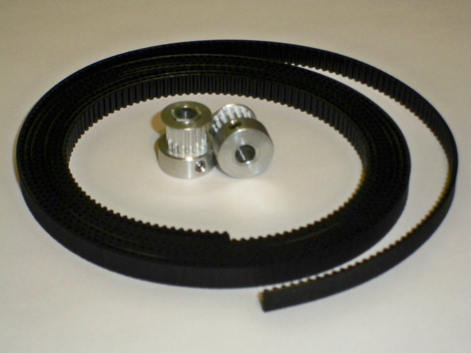
It was $20 bucks, and there was enough belt to do both the X and Y axis, it was a US shipper and to their credit it did arrive very quickly. I replaced the Y pulley and belt. I had a bit of trouble tightening the really small grub screws (1.5mm hex socket) but soon I was printing pretty again! For about a day. Well that trouble I had was real, I couldn’t seem to get the screws in far enough to really engage with the Key in the shaft of my motor. I tried tightening and reassembling, could print ok for a day or two, then I had to do it all over again! When I took it off, I noticed that the grub screw was also made out of aluminum and the hex recess was not a thing of beauty anymore. I managed to get it off, and started to think I needed to find a quality replacement.
I don’t usually think of Adafruit as a place for mechanical parts but I do know them as selecting the best stuff. I also noticed that they were carrying some CNC components. By now I was very frustrated, and in a hurry, I remembered my local electronics store (YouDoitElectronics) carried a number of Adafruit items, so I went there and bought the last 5mm bore GT2 20 tooth pulley:

This was clearly a higher quality part and also a larger diameter, which I think will also help with the slipping (it still fits fine. Adafruit sells a larger one that I think you’d have to redo the belt guides to make it fit.) The grub screws are bigger (2 mm hex recess) which seemed to accept my hex key snugly and had no problem going nice and tight on the shaft. While time will tell, I’m very encouraged that this time I actually made the right decision. After recalibrating Y (as I said, different diameter and number of teeth) I’m printing reliably again. I’m going to put another one in my next Adafruit order and finally replace the X axis (though I’m not currently having any problems.)
By the way, I ran into Brook Drumm (Printrbot Inventor) at the Open Hardware Summit, and related my woes (before I found the Adafruit gear, and while I was temporarily experiencing GT2 bliss) . He sympathized and said he wished when he started out he used at least injection molded gears/pulleys. Current model printrbots do not use 3D printed pulleys.
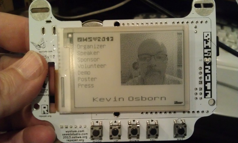
As you know, my Wyolum buddies and I partnered up with SeeedStudios to make a really cool e-paper badge for the Open Hardware Summit which took place last week. We wanted some cool ways for people to customize their badges. Justin created a great simple program for converting images (wifit.py) and I leveraged that software to create a photobooth.
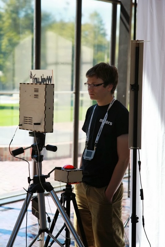
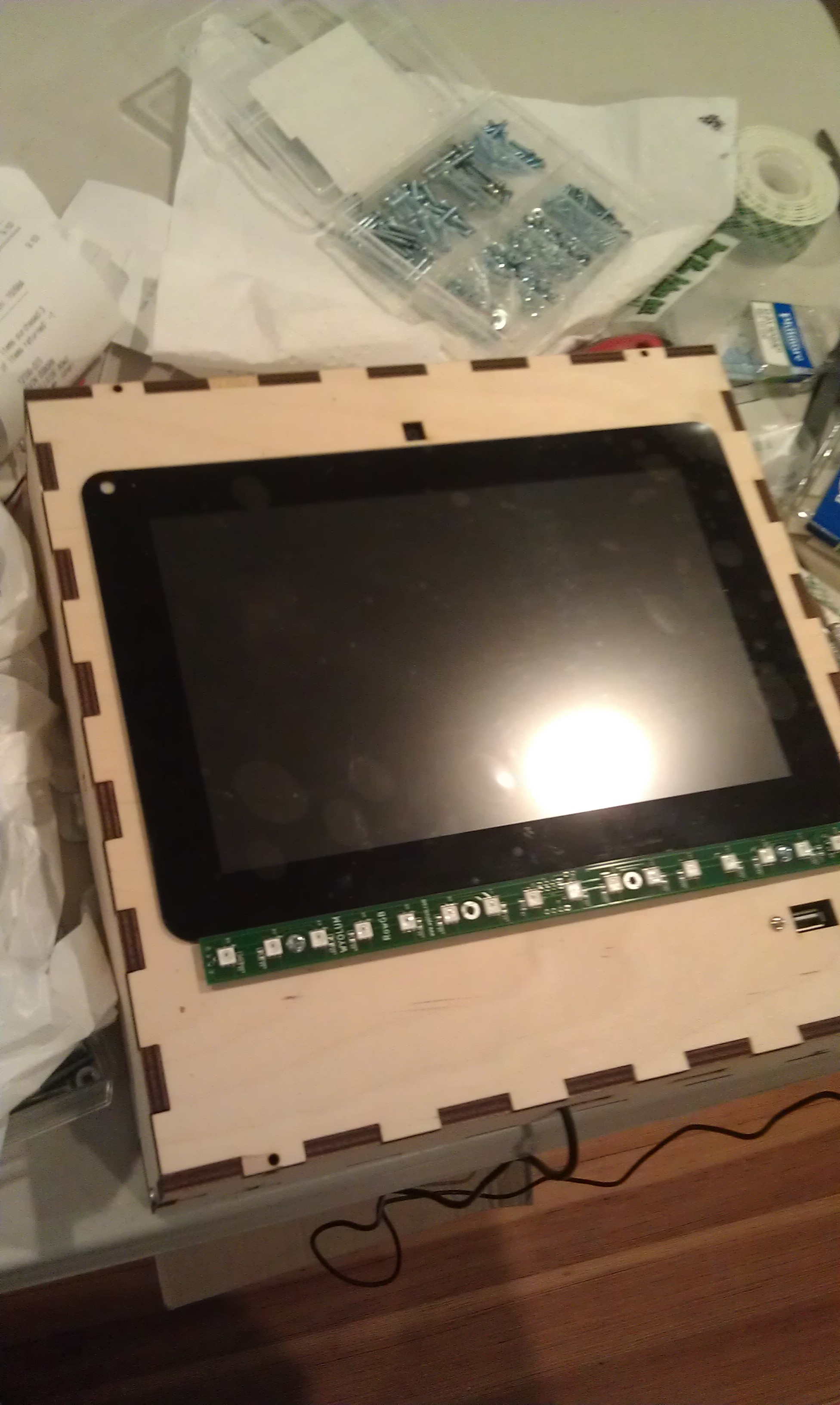
My friend Michael Castor at Makershed built a cool tablet from the Raspberry Pi, and he told me about the nice 10.1″ LCD display and HDMI adapter he found from Chalk-elec.
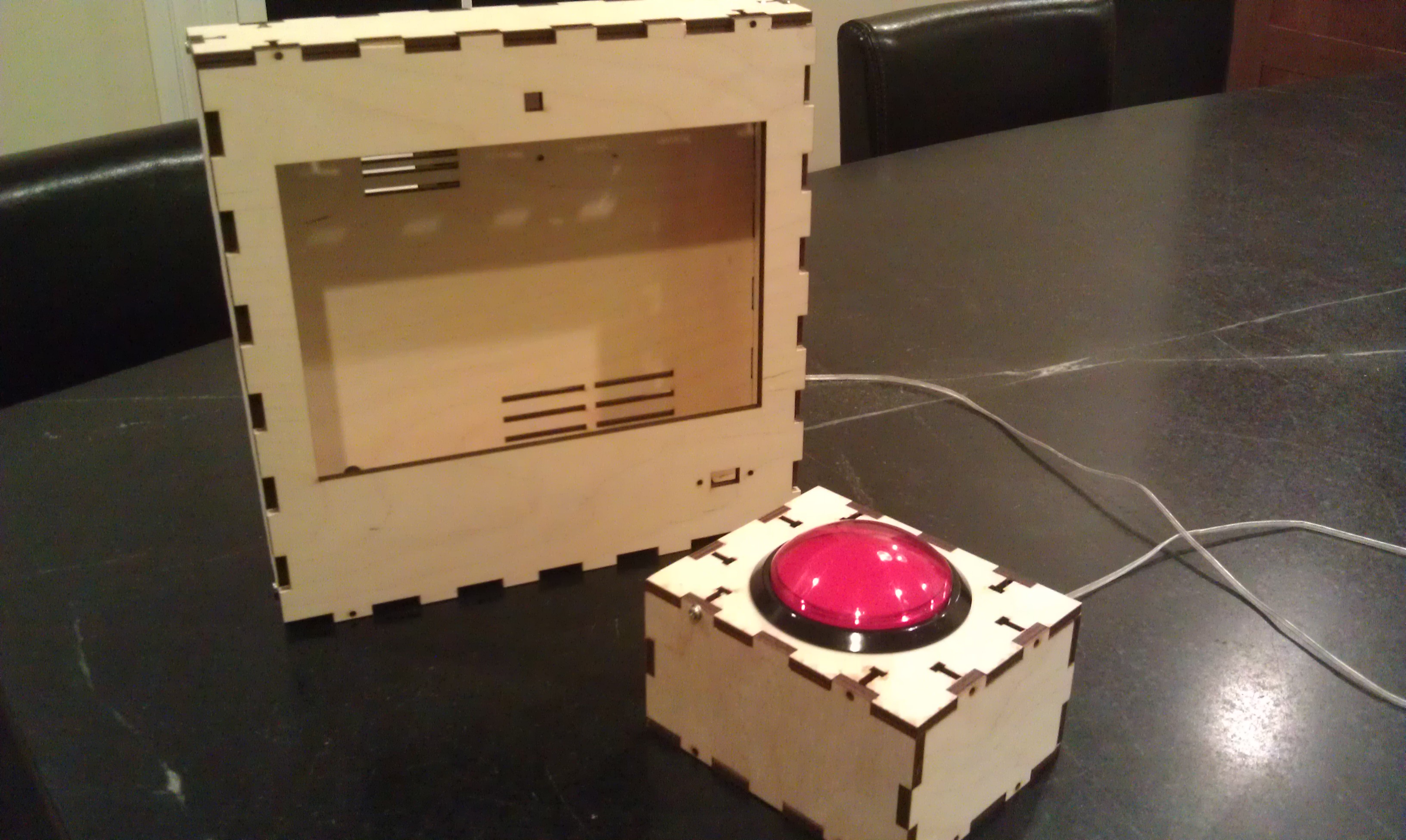
I ordered one, and started figuring out how to put the whole thing together. I also got a big red button from Adafruit. I have been playing with the Raspberry Pi camera and it’s perfect for embedding in a project like this, even though the software is a bit primative at this point (no video for linux drivers, etc.) I used our own AlaMode to read the button and use one of our WS2811 arrays to do a visual countdown before taking the picture.
I’d never really designed anything for laser cutting, and this was my opportunity! I used Inkscape, with the T-slot extension written by Justin. I got the box cut at Einstein’s Workshop (a family oriented makerspace in Burlington, MA.)
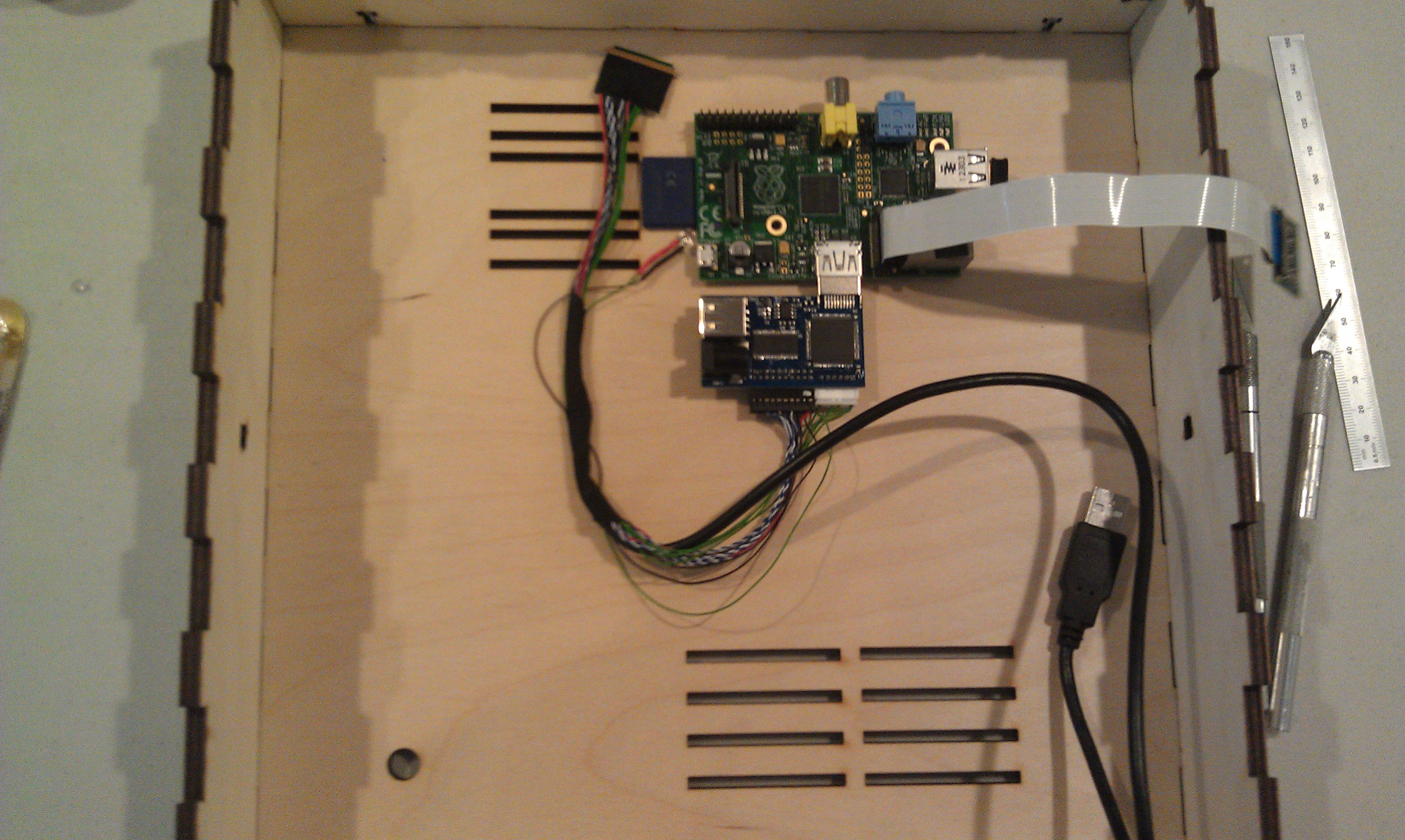
Next, I laid out the components. The trickiest parts were the LVDS cable (though it’s pretty generous) and the Raspberry Pi Camera flex cable.
One really sweet thing about the Chalk-elec hdmi adapter is that you power it, and there’s a USB power port to power the Pi.
Attaching the LCD to the case is a little nerve wracking, as like most tablet screens, it’s intended to be glued in. I used 3M permanent mounting tape (really not tape but adhesive on a backing roll.) It’s really difficult to cut with scissors (it sticks to everything) I made the mistake of putting it on the bezel and trying to cut it with an X-acto knife. I scratched the paint on the bezel, but I managed to fix it with a sharpie.
The better approach turned out to attach it to the opening, and cut along the opening.
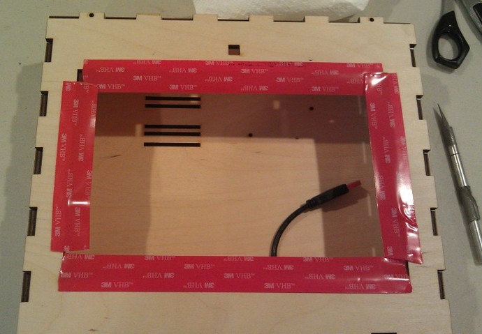
After trimming I added the LCD, and the USB panel mount jack.
I had to drill a few holes because I hadn’t completely planned ahead, for a jack for the switch box (used a 1/4 phone jack and plug) power, and the 16 pixel LED array.
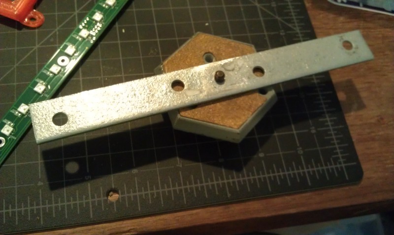
I had planned for it to swivel on the sides from two carriage bolts with wing nuts. This meant making a stand, and I didn’t want it to be just a couple of 2×4’s. Also I was running out of time so I took Justin’s suggestion and made a tripod mount for it. More holes…. And a mending plate from the hardware store. Fortunately I have a set of cheap taps from Harbor Freight, so it was pretty simple to drill the plate and tap it (1/4-20) to accept a tripod mount.
Getting it hooked up with the short cables is a little tricky, but there’s room to get your hands in there:
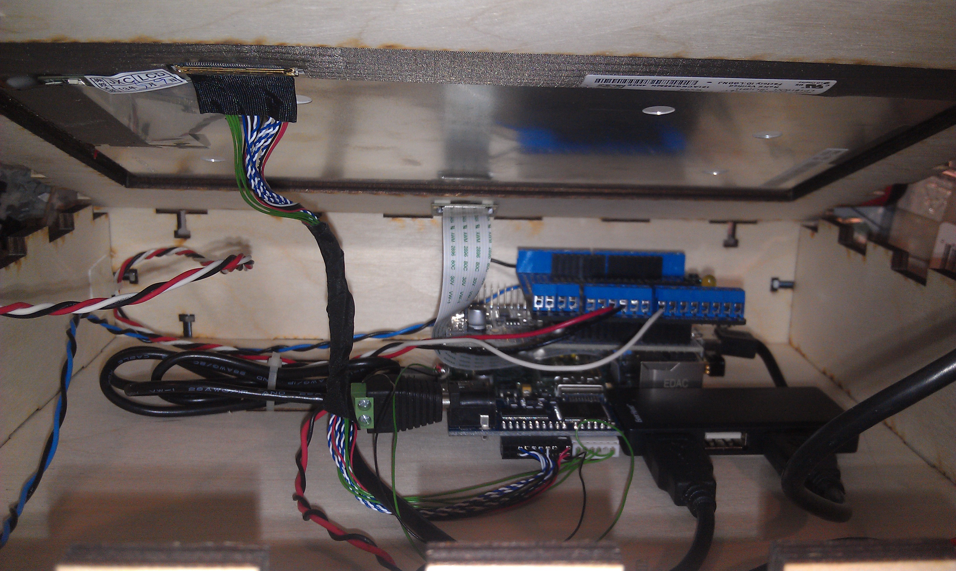 I
I
I used a proto-screw shield to make it easier to hook up the button and LED leads. As you can also see, there’s a small usb hub inside too.
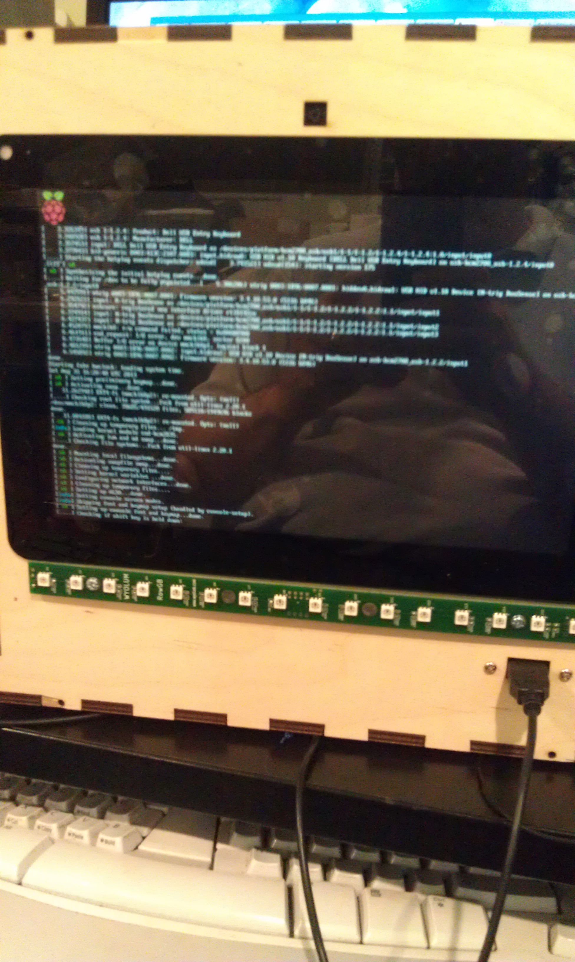
I booted it up:
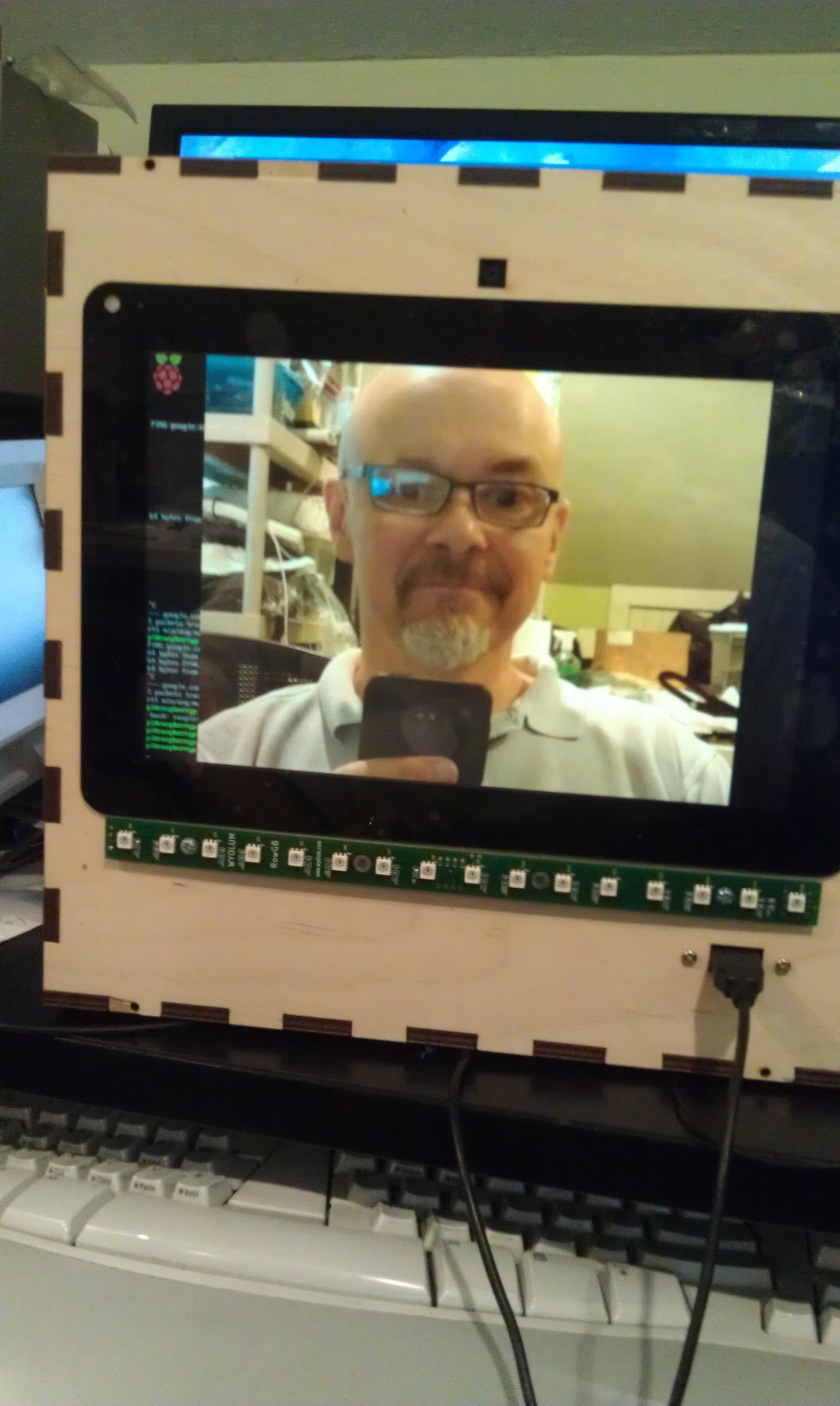
and then hacked Justin’s Wifit program to take a picture:
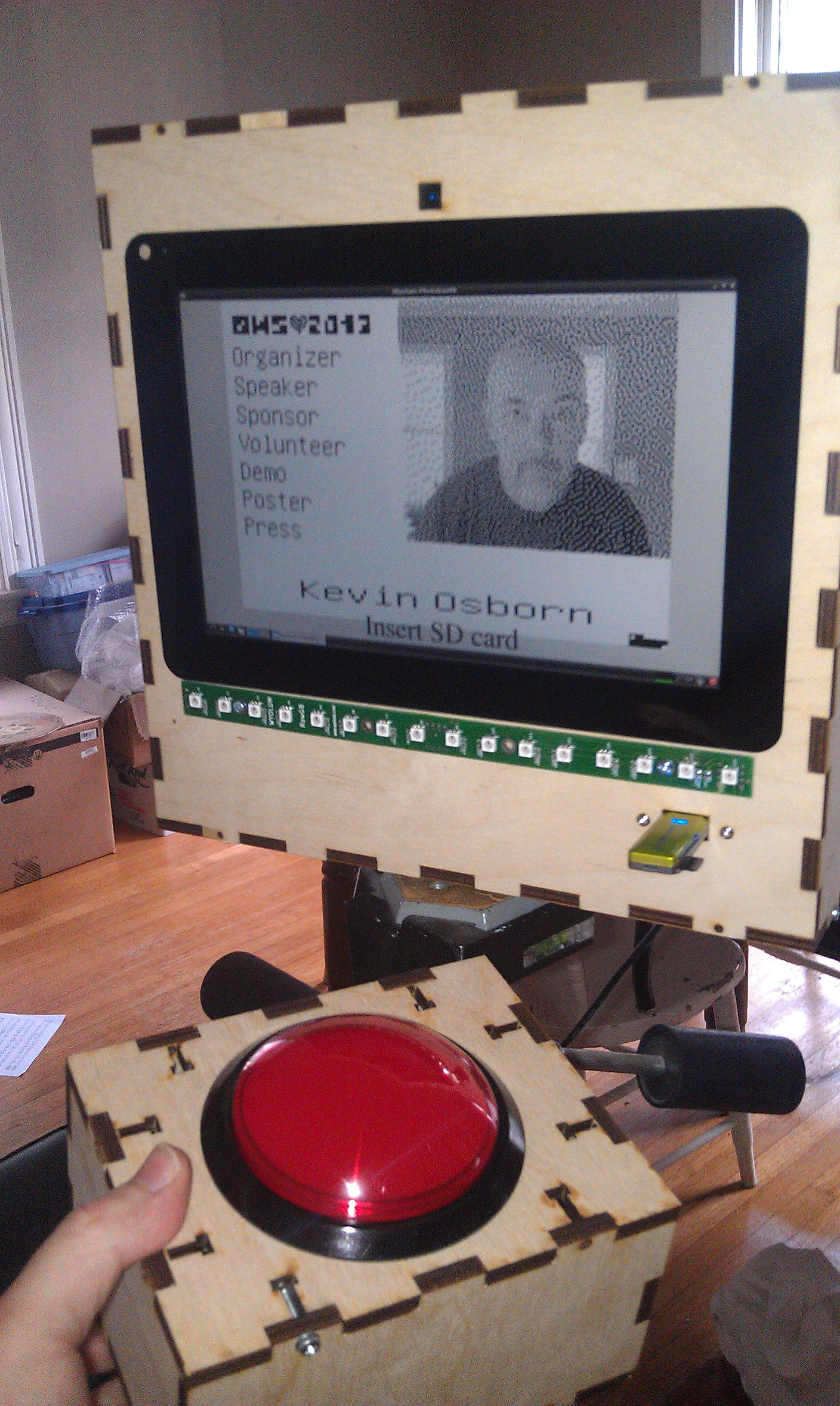
Justin then created a more kiosk-y gui, and I ironed out a few things with the Arduino code for AlaMode. The gui checks to see if an sd card is mounted, and when it is, it sends an enable command to the button and prints on the screen “Press Button when ready” The AlaMode then monitors for the button, and when pressed, sends the signal to take the picture and begins counting down on the LED strip. You can find the code in our github repository: https://github.com/wyolum/EPD
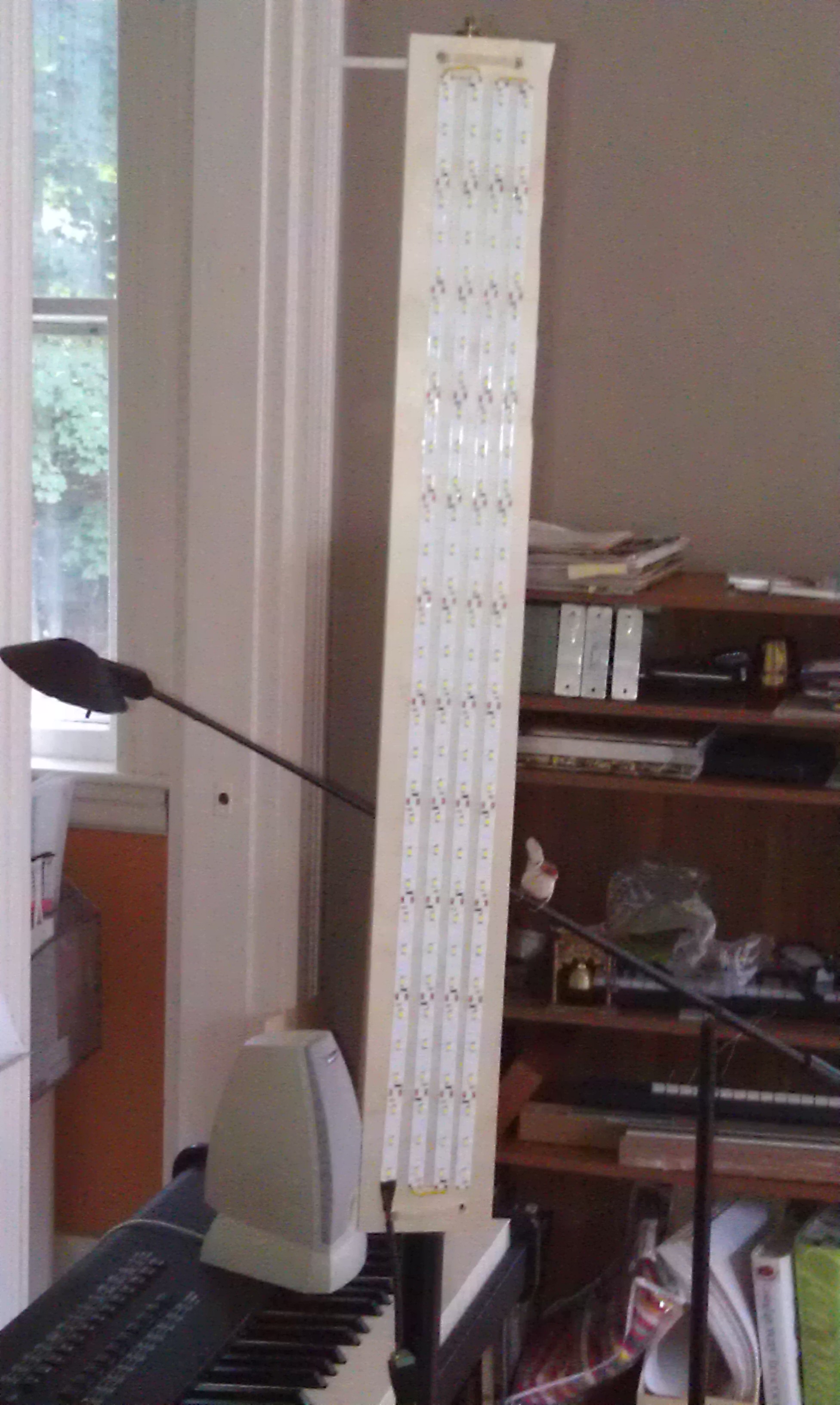
I tried also using the LED strip as a flash, and it worked but made sort of ghastly underlighting like a camp flashlight! So I took some cheap chinese led strip I had around (about $12 for 5 meters) and made a light panel:
And the finished product:
And on the badge:
 I’m thinking of modifying the code to upload higher res pics to the Internet with an imprint, or printing them on a portable printer I picked up at a yard sale!
By the way, I left the Raspberry Pi’s wifi dongle attached, as it made it much easier to debug with SSH from my laptop. That said, I did also plug another hub into the one exposed port to use a keyboard and mouse (even though the touch screen does work!) If I had to do it over again, I might bring at least one more port out for other devices.
You’ll notice in the first picture, the Wyolum Logo across the top. Elizabeth Shaw cut that for me and delivered it the morning of the OHS, and it fit perfectly!
My friend Nick asked if we could find a way to create enhancements to the fantastic, but no longer made Lazertag Team Ops system.
Many people believe that this was the Pinnacle of consumer lazertag, and I tend to agree. In addition to working better both indoors and out, it could host games where it kept track of the scores of multiple players.
Nick and his friend Max came over and we were totally successful! Here’s a brief video showing our results.
[youtube]http://youtu.be/x3LsPc1kz2I[/youtube]
First we looked up what was known about the protocol. I found this:
http://web.archive.org/web/20090304155723/http://lasertagparts.com/ltto.htm
via the LTTO (LazerTagTeamOps) Yahoo group. As you can see the page is no longer in service, but the archive still has it.
Here’s the cool diagram that they created in the past, apparently based on Aaron Nabil’s reverse engineering effort:

Of course it’s easy to say this now, but the protocol was pretty easy to decode by looking at the output on a scope. The only difficulty I had was capturing just the shot, as the dome is constantly shooting out messages saying what team, etc.
Here’s an example of a shot that is created by our program:
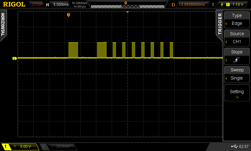
you can see that it uses a 38 kHz carrier (to distinguish it from random IR noise. Fortunately Ken Shirriff wrote a terrific IR Remote library for the Arduino. It’s not really well documented, but there is a sendRaw() function that we used to send the actual timings for the shot. Grab his library here. The library uses preset pin numbers for the LED output, but you can change them in the library itself, you just need to use one of the PWM pins as he uses the timer function to create the carrier frequency.
[code]
unsigned int shootOne[] = {3000,6000,3000,2000,1000,2000,1000,2000,1000,2000,1000,2000,1000,2000,1000,2000,1000};
// the one confusing thing with the irsend.sendRaw command is that the last argument is labled hz, but it’s really
// kiloherz. The lazertag team ops uses the common 38kHz frequency.
irsend.sendRaw(shootOne,sizeof(shootOne)/sizeof(int),38);
[/code]
For the TV-B-Gone, I modified the original firmware to send out the appropriate pulses, similar to my previous hack for camera remotes. The V1 firmware uses uncompressed codes, so that is what I started with.
Grab the example code zip here, and let me know on google+ if you build anything with it!
Also if you want to use Git to pull the code (whether or not you want to fork) it’s all checked in to the baldwisdom github repo:
https://github.com/osbock/Baldwisdom