Using New tools on old parts…
Very early in my career, I lucked out and got a job at General Computer Company in Cambridge. GCC had a contract with Atari to write games for the 2600, and eventually were tagged to create their next generation system, the Atari 7800. I worked on 2600 Joust and Kangaroo, and also on Centipede for the 7800 as well as test code for the hardware and a sound driver that was used in several games.
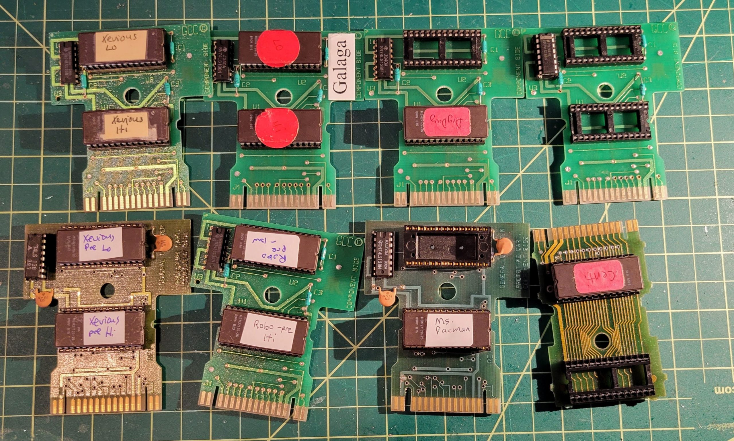
We were given 7800’s from an early production run, and I recently found mine in my attic, and dragged it out, and hacked it to have a composite output. I also had been carrying around these EPROM carts for many years, and I wanted to see if I had anything “interesting” or special.
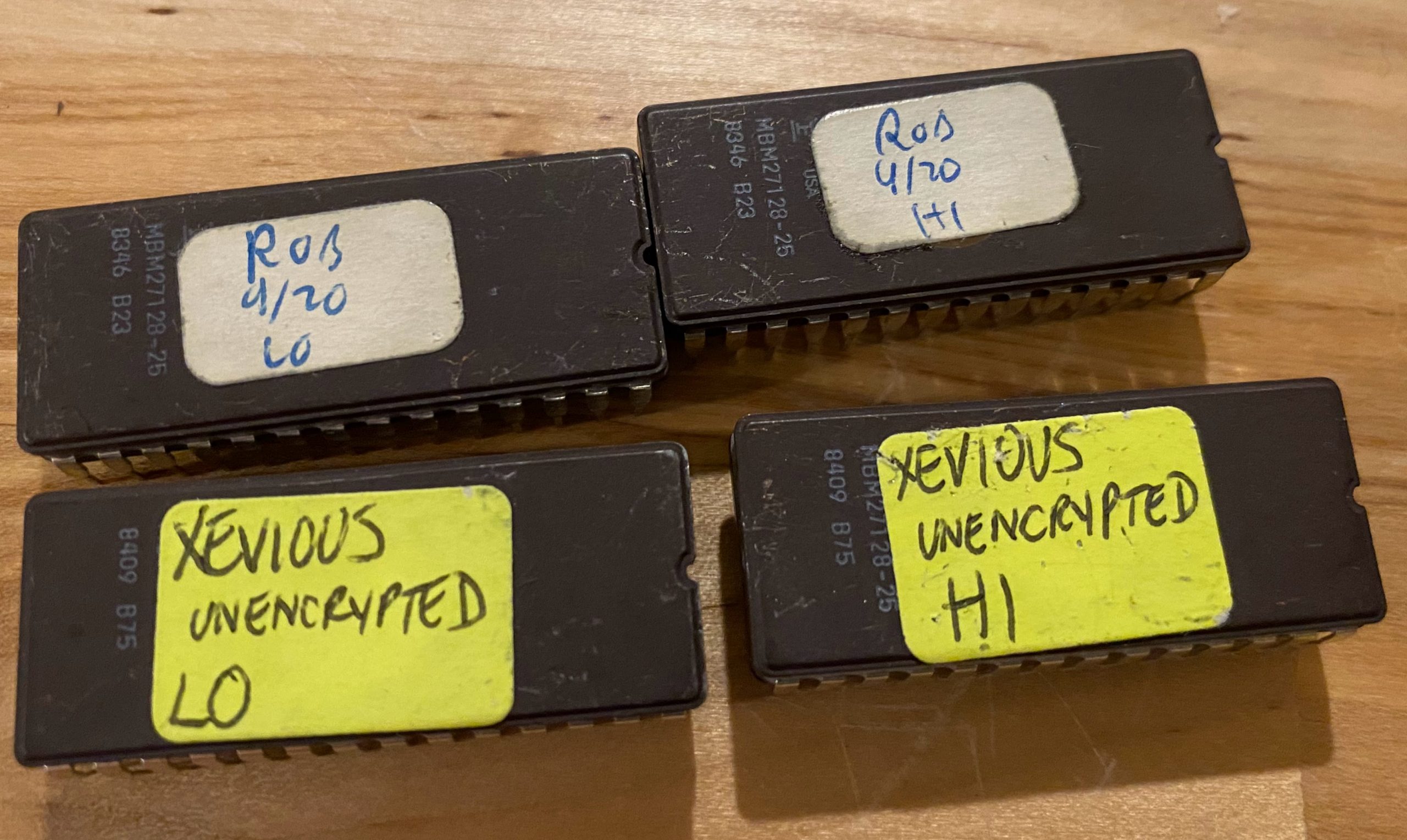
Once I got my 7800 running, many of the cartridges just worked, but there was one set that was labeled ROB 4(9?)/20 (probably Robotron 2084 written by my friend Carlos Smith) and another labled Xevious UNENCRYPTED (written by my friend Tom Flaherty). Neither worked in the 7800, and the Xevious one told me why it didn’t work: It said unencrypted (which was technically un-signed, but that’s what we called it back in 1984).
I did some research, it turns out nobody uses EPROMS anymore, and most non-volatile memory in modern electronics use flash. Back in the old days we had a very expensive Data I/O gang programmer, and even on ebay these days, they are still quite expensive. Fortunately there’s lots of interest in vintage electronics (everything from old home computers to old engine computers) There is (of course) a chinese company that makes a relatively inexpensive line of programmers called Xgecu. Unfortunately, using them requires you to use a somewhat suspicious Chinese download program that only works on Windows. I’m a Mac and Linux guy these days so that wasn’t going to fly. I did find out that two of the older models that they make were reverse engineered by David Griffith and he wrote an open source command line utility called minipro https://gitlab.com/DavidGriffith/minipro.
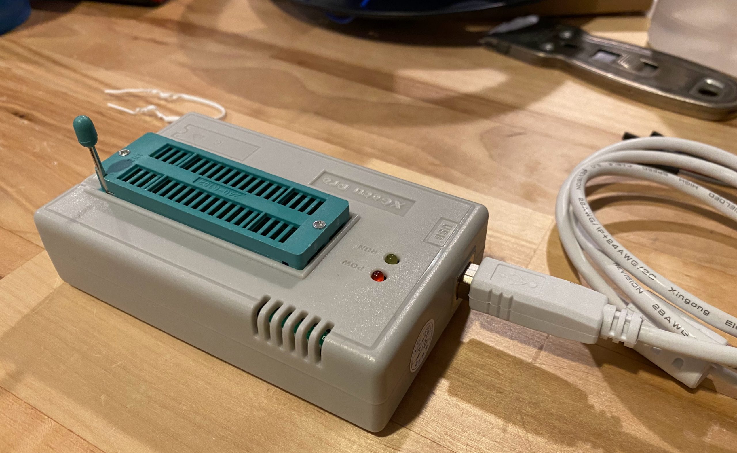
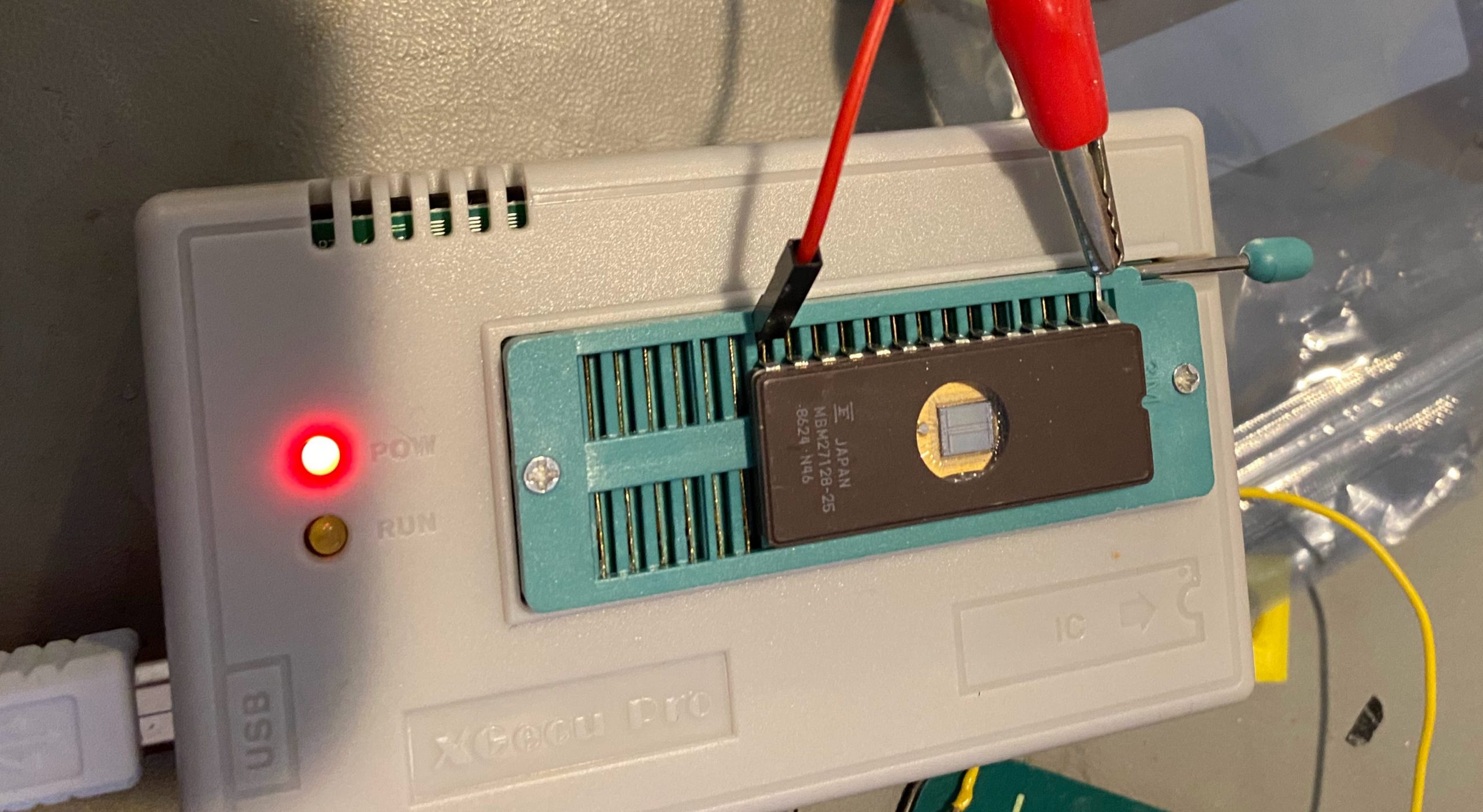
Unfortunately the current shipping version of the Xgecu programmers aren’t supported by minipro (Conversations I found online indicate that David tried but ran into difficulties because the manufacturer was actively trying to keep people from finding out how it works. I searched and found that Jameco was still selling the TL866II+. It was a little more expensive than the very few chinese sellers I found that carried it, but I was impatient and ordered it from Jameco (besides, Jameco is grate for a lot of cool stuff!) I got it in a few days and I was able to read out the EPROMS from my development carts.
It took a little research (a topic for another post) but I figured. out how to assemble the bits from the EPROMs into a form that was playable by the modern Atari 7800 emulator A7800. Most of the games played, including my two “unplayable” games (The emulator doesn’t check the signature). I didn’t check all of them, but a few I did a binary comparison with downloads of the release ROMS and they were identical.
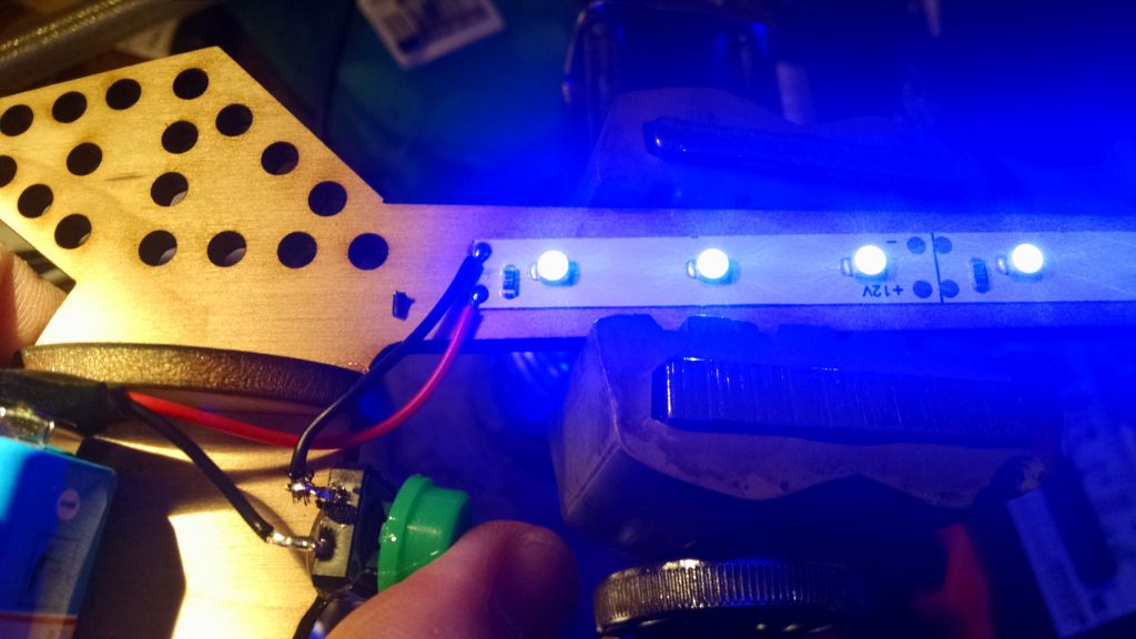
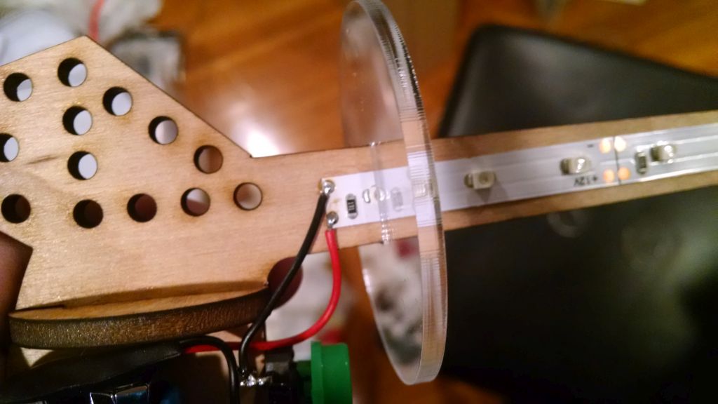
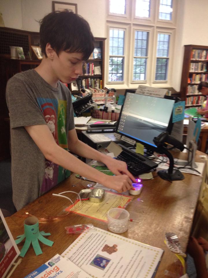
My first problem, I didn’t have any blank EPROMS and I didn’t have an EPROM eraser. EPROMS use strong, short wavelength. (250nm) UV light. I tried a UV lamp I have used for “retrobrighting” old plastics, as well as a UV flashlight, but no luck. I wondered if one of the many phone “sanitizers” that became popular during the pandemic would work. It turns out there are junk ones, (using LEDS) and good ones (with real tubes) and the good ones are pretty expensive new, but it turns out there are lots of these on Facebook Marketplace, and I was able to get the “Phone Soap” UV sanitizer for a really good price.
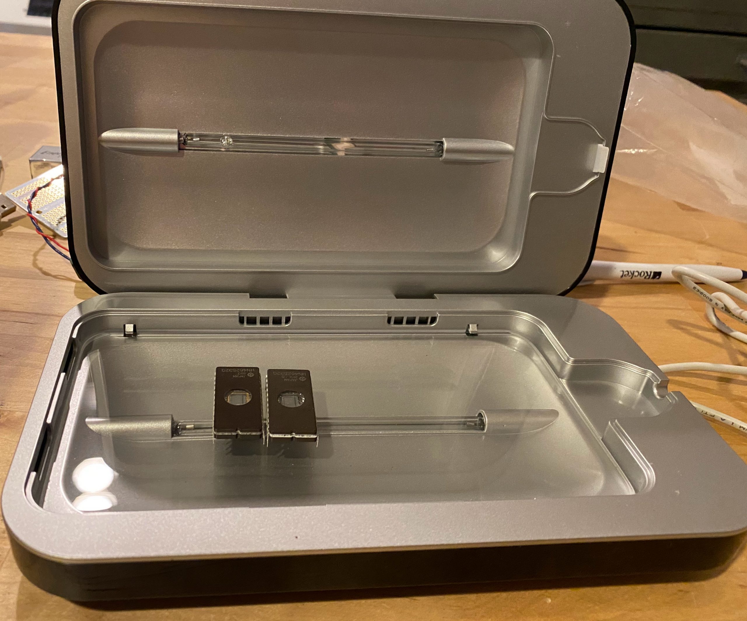
It totally wipes the EPROMS in it’s normal 10 minute cycle!
Using the a7800basic/7800sign command, I was able to verify that the Robotron and Xevious ROMS were unsigned, I signed them and was able to burn the Xevious ROMS and play them on the actual Atari 7800!’
It turns. out, I got lucky. I started trying to burn the robotron ROMs and I got lucky again with the first one, but all the rest Failed to verify after only writing one or two bytes. I thought, maybe they are just old and tired, I tried putting them through the eraser multiple cycles, and still fail. I ordered some new blank ones from Jameco, and they all had the same error!
Time to hit the datasheet
I noticed that the programmer reported the pulse time , VCC, VPP and VDD voltages for programming.
It was reporting VCC, VDD = 5V, VPP=18V and pulse time 200 ms. The first thing I noticed was that the datasheet says 50 ms for the programming pulse, and I tried changing that parameter, no luck. It also said VPP = 21 V and NO DICE! that voltage wasn’t available on the TL866II+ ! (note, that if you look at the same part number from different manufacturers, there are a wide range of acceptable voltages.)
I wondered if you could separately apply that programming voltage or if it needed to be in step with the pulses. The second would definitely be possible, but in terms of time, it might be cheaper to try to find another programmer (the older model could go to 21 V).
I bent out the VPP pin and stuck a wire in with the gnd pin and applied 21V with my bench power supply.
It worked, but bending the pin would not be a strategy I could use very many times. I ordered some ZIF sockets, but as you know, I’m impatient, so I found a 28 pin (narrow) socket, and cut it in half and soldered it up on an adafruit perma proto board.
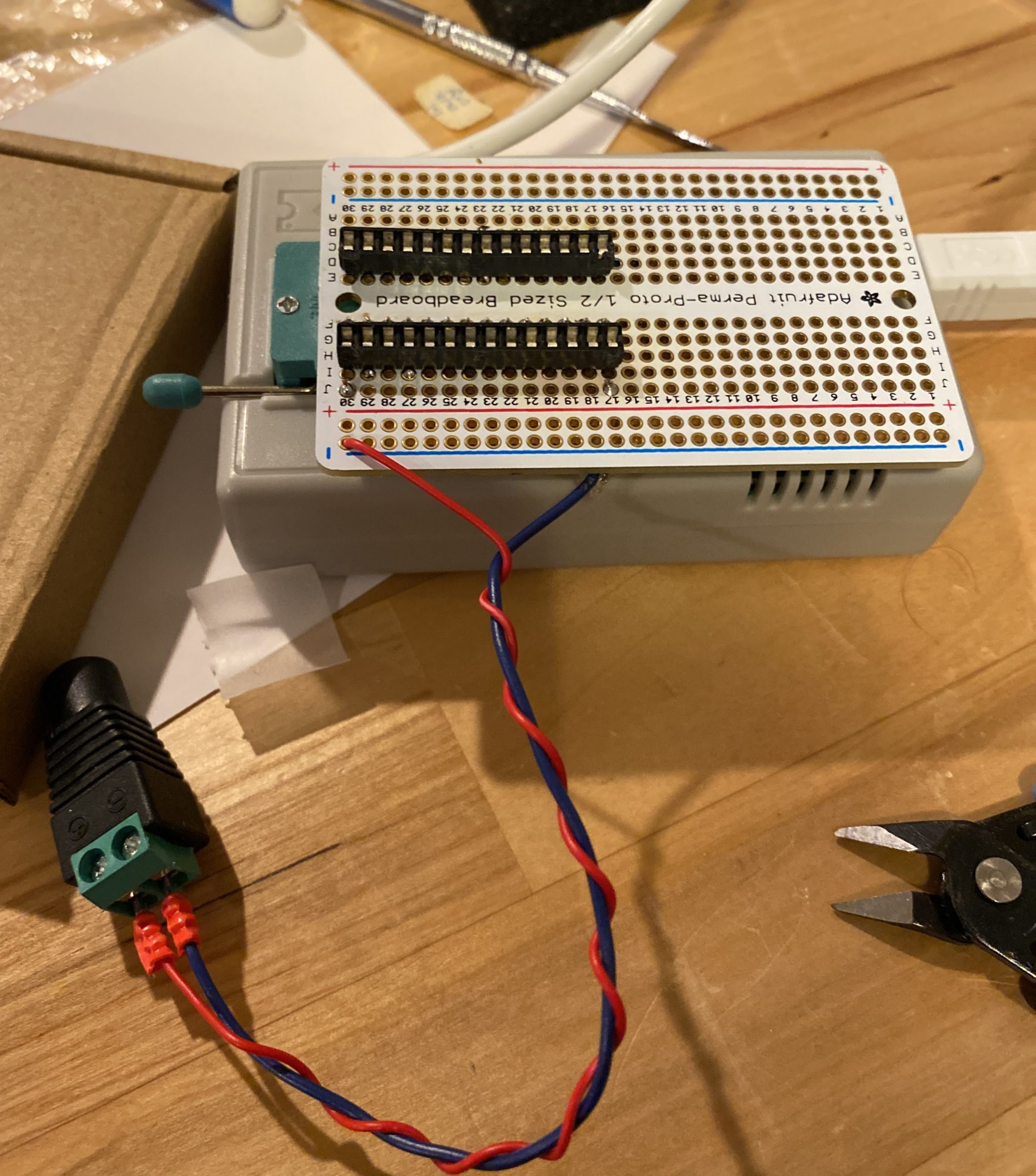
It works very reliably! I was finally able to burn the Robotron roms and play them!