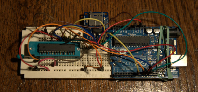
I thought I’d try something new with this project. Write about it as I go along, revealing all the mistakes and false starts, etc. and not wait for it to be finished. Heck, it might never be finished!
This project was inspired by the various arduino-ISP shield tutorials out there. Evilmadscientist.com has an excellent shield, and Adafruit has a do-it-yourself tutorial. These generally make the arduino into an STK500 compatible USB programmer, and you need a computer to burn the chip. I thought, why not make a shield that had a micro-sd card on it and push a button, and bang! chip programmed!
Not many people probably need this kind of production, but I thought I could learn a few things.
Now Adafruit has another cool project based on another project called Optiloader, where you can embed a program in the Arduino program and burn standalone, but the program has to fit on the Arduino along with the programming code.
Here’s my basic plan of attack:
- Decide what I want the project to do. Here I brainstorm a bunch of features and put it into a google doc. I then prioritize what I want for the first iteration.
Here’s basically what I came up with: - Program chip from files on SD card
- Read chip to files on SD card
- Maintain ArduinoISP functionality?
- Log ArduinoISP session to card?
- replay ArduinoISP session from card?UI
- Read(read from chip to SD card) button
- Green Light indicator
- Write (program chip from SD card)
- Red LED indicator during/flashing green at finish
- Error indicated via flashing red
- If USB is connected, information printed via serial
- Read(read from chip to SD card) button
- Order any parts I need. In this case, I bought a micro-SD breakout board from Adafruit. This has a voltage shifter chip to protect the cards (which use 3.3 V from the 5 V Arduino signals. I already had a zif socket.
- Breadboard the project. As you can see above I did the minimum. For the “shield version” I’ll probably also add some buttons and indicator LED’s
Here’s the wiring to the atmega/ziff socket (from the adafruit tutorial):- Pin 1 to digital 10 – Blue
- Pin 7 to 5V – Red
- Pin 8 to Ground – Black
- Pin 9 to digital 9 – Gray
- Pin 17 to digital 11 – Brown
- Pin 18 to digital 12 – Orange
- Pin 19 to digital 13 – Yellow
- Pin 20 to +5V – Red
- Pin 22 to Ground – Black
SD Breakout Wiring: - GND to Ground
- 5V to 5V
- CLK to Arduino Pin 13
- DO to Arduino Pin 12
- DI to Arduino Pin 11
- and CS to pin 8 (important as this has to be different than the line used to select the 328!)
- Test the individual parts to make sure they don’t interfere with each other. I loaded the Arduino ISP code, and programmed an atmega328, and I loaded the SD library and read some files off the card. You’ll also need to change the code line in the SD example code to use the different chipSelect line. I learned/realized a couple of things:
- I should probably include a crystal/oscillator so that you can burn fuses that require an external oscillator (like the Arduino itself)
- One of the SPI lines is tied directly to the SD card activity light. This means that that light will flicker when the chip is being programmed.
Create an Arduino Shield for standalone programming of atmega chips from files stored on a micro-sd card. First iteration will handle one program on the card (selection of files would require UI)
Functions:
This is as far as I’ve gotten so far. Next:
- Write the code to read Intel Hex files from the card
- Define and write code for a file for fuses
- Adapt Optiloader code to write data read from the card
- Implement user interface
