[youtube]http://www.youtube.com/watch?v=PAX8vhzv4dE[/youtube]
[youtube]http://www.youtube.com/watch?v=PAX8vhzv4dE[/youtube]
A lot of libraries and schools are getting 3D printers, and also, if you personally have one and want to show it off, it’s hard to have people do things in a reasonable amount of time. 3D printers are just inherently slow.
One activity I came up with that allows you to do personalized 3D printing, is to, well, do 2D printing!
We’ll learn how to take some characters, make them into a flat 3D object that can be printed quickly.
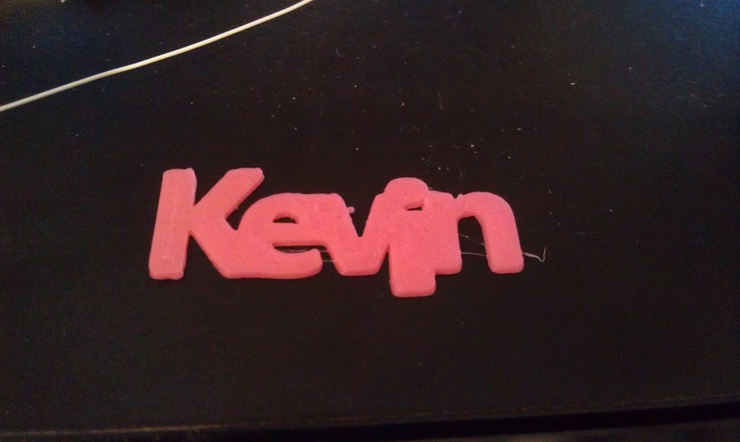
This little logo printed in about 2 minutes on my Printrbot Plus.
We’ll be using inkcape (a vector drawing program) from http://inkscape.org, and OpenSCAD (a 3D drawing language) from http://openscad.org. Download and install (they are both free and open source!)
Here’s a video walk through, but details are also written below.
[youtube]XnpnsKFmvZE[/youtube]
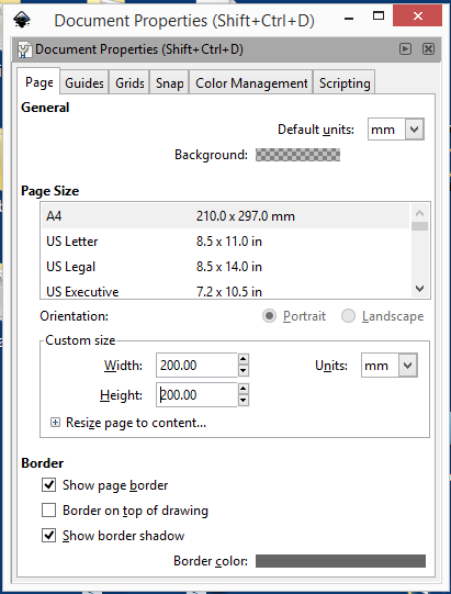
Open a new document in inkcsape. I like to change the document properties to use a real measuring unit, so I can tell how big things are. Change the default units from px to mm, and the size in mm units to your print bed size. In my case 200×200.
Using the Text tool, type your name. I use 72 pt (about an inch or 25.4mm tall) and a font that is fairly blocky. If you want to print larger, you can use more filigreed fonts, but for this exercise, the point is speed, so we need something that will print well small.
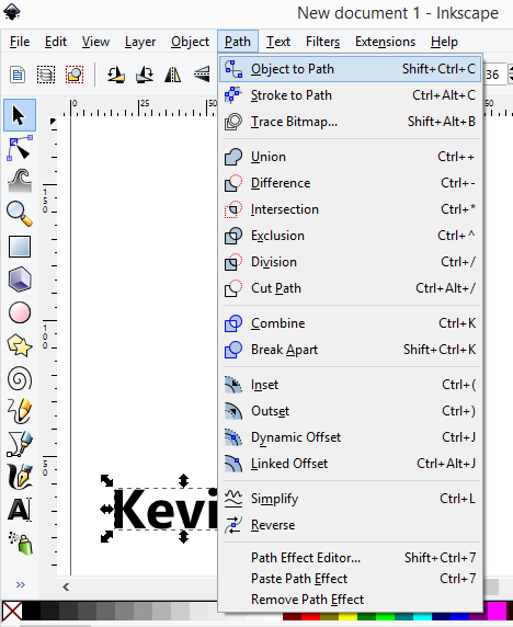
Select the name using the arrow tool, and then path/object to path:
Next click on the second icon down (below the arrow) that is edit path by nodes.
We’re not quite there yet, as we have a path, and we need polygons. Paths include things like splines and other curves. If you grab one of the handles you can see we don’t have straight lines.
It can be a little frustrating working with some of these tools, but there’s a secret OpenSCAD only understands polygons in a DXF file. If you have any splines or arcs, it just ignores them, sometimes giving a warning, sometimes not.
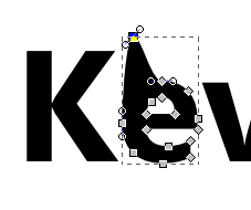
Shift select all of the letters while in path editing mode.
The key to converting any 2D vector drawing is to make sure to select all the segments and click the convert to lines button. Curvy letters like the lower case E in my name will reduce to angular uglies, so , you can add points by clicking the add points button a couple of times.
Next, click on make selected segments lines (make sure all the nodes are selected. If they are grey, they are not selected.)
Next, it’s a little tricky. Click on the second letter in path edit mode, switch to select/move mode (the arrow) and move the letter to touch the first one. Repeat. For the i, I moved it down so the dot was also touching.
At this point we have a bunch of polygons, and OpenSCAD may or may not be able to render it. You can make sure by selecting all the paths, and then perform a Path/Union menu function to simplify the shape.
It’s best to move the whole thing down to 0,0. You can do this with the mouse, or just type in the x,y box.
Next, save it as a DXF file (not the default SVG), in the same directory where you’ll store your openSCAD file.
Then it’s a simple matter of linear_extrude(height=2)import(“kevin.dxf”);
The dxf file has to be in the same directory as the scad file, so you have to save the scad file first before you run it.
It’s probably best to select print quality settings that don’t take too long, but still look ok. You can also influence the print time by extruding at a shorter height, but I think one mm is about the minimum for something you can remove without breaking
[youtube]http://www.youtube.com/watch?v=JiCylYs6G0o[/youtube]
I’ve been working with a number of area librarians to create maker and STEAM workshops for their libraries. In preparation for some more advanced workshops, I worked with Nina Taylor, the teen librarian at the Morse Institute Library in Natick, Mass. to put on a vibrobot workshop.
The kids were great, and some immediately took to experimenting, decorating and creating wild things, while others needed getting used to the idea of doing something beyond following directions. Almost all of them said they would come back to do more, so I consider it a resounding success.
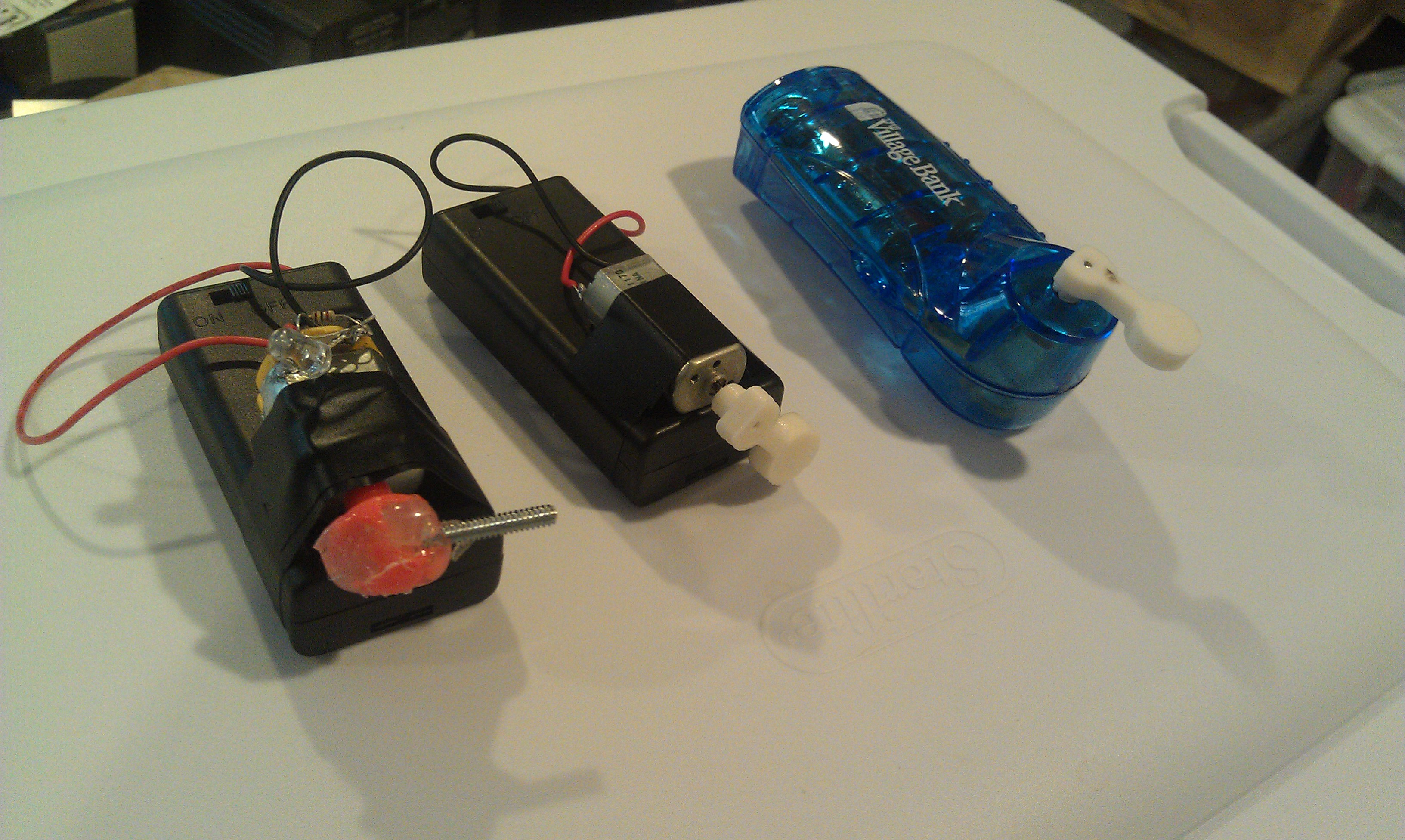
In addition to making Bristlebots (invented by Evil Mad Scientists) and sold as a kit by Makershed, we also made “drawbots” for which I made vibro-packs from salvaged motors and battery packs.
The Makershed kit is great, in that wires are already attached to the batteries, making assembly very easy.
For the drawbots, we taped markers around a cup as legs and then attached my vibro-packs. You can make any motor vibrate by attaching a weight off center to the shaft.
As you can see in this picture, I made one by taking the propeller off a bubble blower toy, and hot gluing a screw in.
I didn’t love this, and was scratching my head when I thought “doh!, I have a 3D printer!”
I created a very simple model in Open SCAD, that was adaptable to the various salvaged motors..

You can download the source here, or from Thingiverse. You can use the customizer widget on thingiverse, but it’s much faster if you have OpenScad installed and you tweak it yourself!
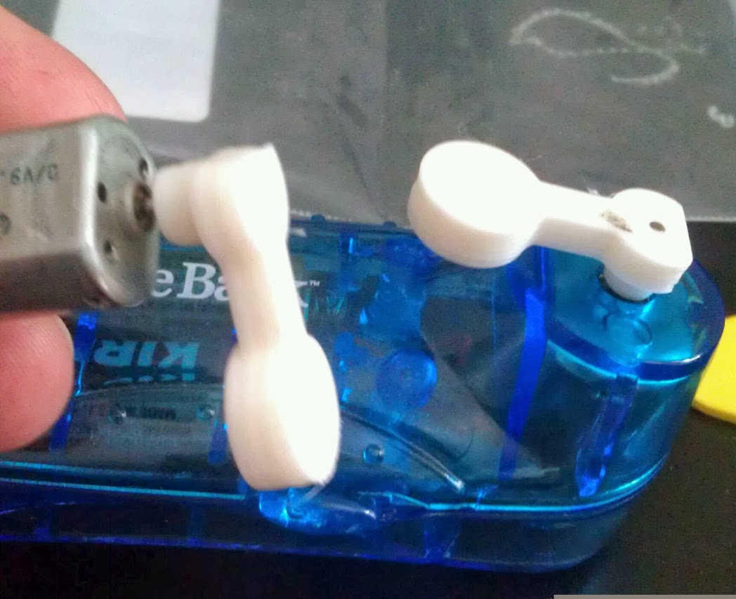
I’m most proud of the the free fan (ok, I lost the fan part) from a local bank, but it makes a great, all in one battery pack, switch and motor!
It’s a fantastic introduction to making, so try it yourself!

After many hours of tweaking and fiddling, I was finally getting decent prints out of my first generation printrbot plus that I got used from a friend. I learned a lot about filament quality, differences in materials and the importance of bed levelling. I bought and installed a bed leveller upgrade from Printrbot.com, and printed and installed some belt tensioners.
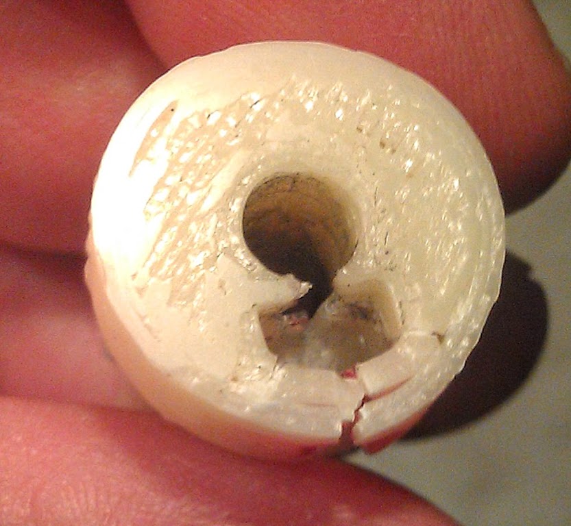
I got a couple of good prints and then pow, every couple of rows would be offset! But my belts were tight!?! ARGH! I took the Y axis apart and found this:
The 3D printed pulley broke right at the set screw/nut retension. It would go with the flow when moving slowly, but a rapid move to start the next layer would cause it to slip. I read a bunch of forum postings, and while there was a “new and improved injection molded replacement” available at printrbot.com, I decided to try and “upgrade” to GT2 belts and pulleys. While the jury is still out on whether or not they actually give you higher resolution, it’s clear that aluminum is probably better than 3d Printed plastic. (or so I thought…) So I ordered two pulleys and a belt off of ebay.
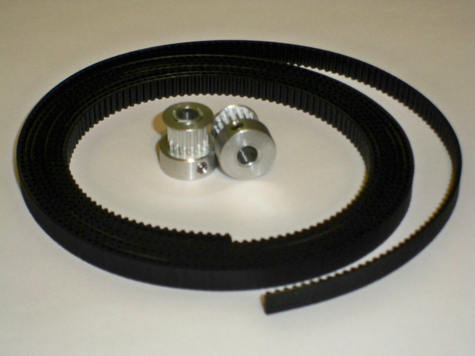
It was $20 bucks, and there was enough belt to do both the X and Y axis, it was a US shipper and to their credit it did arrive very quickly. I replaced the Y pulley and belt. I had a bit of trouble tightening the really small grub screws (1.5mm hex socket) but soon I was printing pretty again! For about a day. Well that trouble I had was real, I couldn’t seem to get the screws in far enough to really engage with the Key in the shaft of my motor. I tried tightening and reassembling, could print ok for a day or two, then I had to do it all over again! When I took it off, I noticed that the grub screw was also made out of aluminum and the hex recess was not a thing of beauty anymore. I managed to get it off, and started to think I needed to find a quality replacement.
I don’t usually think of Adafruit as a place for mechanical parts but I do know them as selecting the best stuff. I also noticed that they were carrying some CNC components. By now I was very frustrated, and in a hurry, I remembered my local electronics store (YouDoitElectronics) carried a number of Adafruit items, so I went there and bought the last 5mm bore GT2 20 tooth pulley:

This was clearly a higher quality part and also a larger diameter, which I think will also help with the slipping (it still fits fine. Adafruit sells a larger one that I think you’d have to redo the belt guides to make it fit.) The grub screws are bigger (2 mm hex recess) which seemed to accept my hex key snugly and had no problem going nice and tight on the shaft. While time will tell, I’m very encouraged that this time I actually made the right decision. After recalibrating Y (as I said, different diameter and number of teeth) I’m printing reliably again. I’m going to put another one in my next Adafruit order and finally replace the X axis (though I’m not currently having any problems.)
By the way, I ran into Brook Drumm (Printrbot Inventor) at the Open Hardware Summit, and related my woes (before I found the Adafruit gear, and while I was temporarily experiencing GT2 bliss) . He sympathized and said he wished when he started out he used at least injection molded gears/pulleys. Current model printrbots do not use 3D printed pulleys.