Monthly Archives: November 2011

Arduino Auto-programmer part 1

I thought I’d try something new with this project. Write about it as I go along, revealing all the mistakes and false starts, etc. and not wait for it to be finished. Heck, it might never be finished!

This project was inspired by the various arduino-ISP shield tutorials out there.  Evilmadscientist.com has an excellent shield, and Adafruit has a do-it-yourself tutorial. These generally make the arduino into an STK500 compatible USB programmer, and you need a computer to burn the chip. I thought, why not make a shield that had a micro-sd card on it and push a button, and bang! chip programmed!

Not many people probably need this kind of production, but I thought I could learn a few things.

Now Adafruit has another cool project based on another project called Optiloader, where you can embed a program in the Arduino program and burn standalone, but the program has to fit on the Arduino along with the programming code.

Here’s my basic plan of attack:

  1. Decide what I want the project to do. Here I brainstorm a bunch of features and put it into a google doc. I then prioritize what I want for the first iteration.
    Here’s basically what I came up with:
  2. Project Overview:
    Create an Arduino Shield for standalone programming of atmega chips from files stored on a micro-sd card. First iteration will handle one program on the card (selection of files would require UI)
    Functions:
    • Program chip from files on SD card
    • Read chip to files on SD card
    • Maintain ArduinoISP functionality?
    • Log ArduinoISP session to card?
    • replay ArduinoISP session from card?UI
      • Read(read from chip to SD card) button
        • Green Light indicator
      • Write (program chip from SD card)
        • Red LED indicator during/flashing green at finish
      • Error indicated via flashing red
      • If USB is connected, information printed via serial
  3. Order any parts I need. In this case, I bought a micro-SD breakout board from Adafruit. This has a voltage shifter chip to protect the cards (which use 3.3 V from the 5 V Arduino signals. I already had a zif socket.
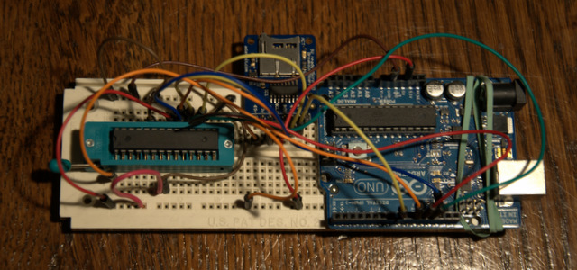
  4. Breadboard the project. As you can see above I did the minimum. For the “shield version” I’ll probably also add some buttons and indicator LED’s
    Here’s the wiring to the atmega/ziff socket (from the adafruit tutorial):

    1. Pin 1 to digital 10 – Blue
    2. Pin 7 to 5V – Red
    3. Pin 8 to Ground – Black
    4. Pin 9 to digital 9 – Gray
    5. Pin 17 to digital 11 – Brown
    6. Pin 18 to digital 12 – Orange
    7. Pin 19 to digital 13 – Yellow
    8. Pin 20 to +5V – Red
    9. Pin 22 to Ground – Black
      SD Breakout Wiring:
    10. GND to Ground
    11. 5V to 5V
    12. CLK to Arduino Pin 13
    13. DO to Arduino Pin 12
    14. DI to Arduino Pin 11
    15. and CS to pin 8 (important as this has to be different than the line used to select the 328!)
  5. Test the individual parts to make sure they don’t interfere with each other. I loaded the Arduino ISP code, and programmed an atmega328, and I loaded the SD library and read some files off the card. You’ll also need to change the code line in the SD example code to use the different chipSelect line.  I learned/realized a couple of things:
    1. I should probably include a crystal/oscillator so that you can burn fuses that require an external oscillator (like the Arduino itself)
    2. One of the SPI lines is tied directly to the SD card activity light. This means that that light will flicker when the chip is being programmed.

This is as far as I’ve gotten so far. Next:

  1. Write the code to read Intel Hex files from the card
  2. Define and write code for a file for fuses
  3. Adapt Optiloader code to write data read from the card
  4. Implement user interface

Black Friday? No! F.A.T. Yes!

For the third year, our family entered in to the mad-crazy collaborative experiment that is  the Friday After Thanksgiving Chain Reaction at MIT in Cambridge. I think the main idea is to create, and not consume, and I love not only being there with my family creating, but also seeing the brilliant creations of everyone else.

As usual we weren’t super prepared (even th0ugh I spent most of the day on Thursday building) and spent almost till the last minute preparing and fixing, and our run wasn’t without the “Hand of God” helping it along, but it was fantastic!

I didn’t get very many pictures, but I’ll tell you about what we did.

The event is emceed by Arthur Ganson, artist in residence at MIT, and Mechanical genius. He has a whole room of his sculptures at the MIT museum, and it’s worth a trip just for that. He also generously helps people out, encouraging everyone, and builds the final link with some sort of theme. This year (the 14th) the theme was Sonnets, and his final piece dropped ostrich feathers one at a time with lines from a sonnet he wrote (it was beautiful!)

Each link is triggered either by a string pull or a golf ball entering your contraption. This year we decided to go for the additional challenge of the golf ball for the first time. We reused a ball run I made for last years event, and added an elevator for the ball made out of Knex.

Here’s the sequence:

  1. First the ball lands in a “chair” made out of Knex, and presses a Lego Mindstorms NXT touch sensor under it.
  2. This triggered the NXT to supply power to a short section of Lego 9V train.  The train steamed forward to…
  3. A brilliant Lego pneumatic switch mechanism design by our 11 year old neighbor and friend Jackson. This pneumatic contraption then fired his new high power laser pointer which….
  4. Popped a black balloon holding steel balls which
  5. Fell on a plate over a switch which triggered an Arduino controlled Silly String shooter. Getting to make this was some of the most fun. Before the event, I hooked it up to a motion sensor and surprised my kids with it. I got the idea while at Walgreens walking down the toy aisle. I thought, hey, I can probably rig a servo to spray that! Of course, googling it first, It’d been done! And cleverly too, so not one to reinvent the silly string shooter, I copied the design (though not the code…) Here’s the instructable that I used: http://www.instructables.com/id/Arduino-controlled-Silly-String-shooter/ by Instructables user Eric Kingston
  6. The silly string sprayed onto a paper plate (decorated as a target by Charlotte!) which pressed a microswitch that triggered another Arduino that used an Adafruit motorshield to run a KNex motor which I spliced into to run the winder to lift the golf ball. I use this shield a lot, for whenever I want to make some scavenged motor move something. For example I once built stuff from cd-rom drives for the kids to interact with in their classroom. Very handy.
    When the golf ball reached the top…
  7. The same Arduino started spelling out a message on the super bright 8×8 LED panel from Modern Device that I picked up at Maker Faire in Rhode Island. It scrolled FAT.. This board has a fabulous library, is super bright, and really easy to use.
  8. The golf ball rolled down several ramps to a makeshift ramp between tables and on to the next table.

Our neighbors contraptions put ours to shame, both in terms of mechanical cleverness and overall finish. The one before us was an elaborate mechanism that shuttled brightly colored golf balls along a track to fall into a bucket, the weight of which eventually powered a putter to put the travel ball on to our section.

I encourage everyone to come and to build! It happens every year, and it doesn’t take much to participate (some links are little more than domino runs) and it certainly gets you away from the shopping crowds into a much better crowd!

Afterwards, we hung out in the empty gym and flew our new Air Swimmer (which I highly recommend!)

Woot! Free tool!

Instructables.com is one of my favorite sites, offering step by step instructions for all kinds of projects.

Instructables author Randofo created a cool Arduino shield for programming 8 pin attinys. In a brilliant move to get more instructables submitted, he offered one for free if you submitted an Arduino or AVR instructable. Well, that pushed me over the edge and I submitted my first one:

http://www.instructables.com/id/Turn-a-TV-B-Gone-into-a-super-camera-remote/

And this is what they sent me! Cool stickers and a badge! Now I just have to come up with a Nerd sash!As an added bonus, my instructable got featured on the home page and they rewarded me with a pro membership!

Now that’s the way to develop motivation to provide content!

Since getting the shield, I’ve already hacked it. It can’t program attinys with an external clock, so I added one, and put up this instructable:

http://www.instructables.com/id/Using-the-8Pin-ATTINY-programming-shield-with-an-e/

More Noise: Sound sample

I’m a little reluctant to release this, as the police may use it on the occupy protestors. This is one annoying sound!

It was pretty hard to hear what the circuit sounded like in the video, so I modified it to have a line level output and recorded it on my computer. At first I was baffled, as the volume kept going up and down, and there were weird compression artifacts until I figured out the  sound card in my computer was doing all sorts of noise reduction and signal processing on the microphone input! I turned it off and here’s the raw sound:

Making Noise, learning electronics!

I’d seen several projects on the net to make analog synthesizers, including the classic Atari Punk Console. I’m anxious to design something of my own, but I’m still learning, so I thought I’d start small. While this is not something that hasn’t been done before, I did it entirely from scratch. I read datasheets, and experimented with values for components.

Here’s a little video overview:

I did this project iteratively, first implementing a single oscillator controlled by a variable resistor or potentiometer. The capacitor I chose (220 pF) was somewhere in the middle of the range recommended by the data sheet, though I tried several other values. I have a cheap analog scope, and I could see the oscillation, but when I tried to attach a speaker, it went dead.  I hooked up a piezo element and it could drive that, but it wasn’t very loud. I stuck in a 2N2222 transistor, and used a pot to determine the optimal (loudest) bias resistor for the base, and replaced it with a fixed value.

Next, I replaced the pot with a photoresistor. This was fun, but the tone was pretty boring (plain square wave). I then hooked up another gate to drive an LED. Pointed at the photo resistor, but some distance away, it provides a cool beat, while the “average frequency is determined by the other light hitting the photoresistor. The frequency of the beat is controlled by a potentiometer like in the first circuit.

Here’s the schematic:

One tip: You’ll notice R3 in series with the potentiometer. This is because the pot goes all the way to zero, and at zero resistance the cap won’t charge and discharge properly setting up the oscillation. This sets some non-zero base value that you can set experimentally based on what you want that end of the frequency range to be.

TI MSP430 LaunchPad First Impressions

The DangerousPrototypes Blog had a quick post on a deal that Texas Instruments was offering a Watch/development kit for their low power processors for only $24. I’ll be telling you more about this in a future installment, but while I was grabbing the deal, I saw this neat little development kit for their low-power value-line processors. It cost all of $4.30, includes two processors and all the tools you need to get going.

First, while this is an extremely cheap USB enabled development board, this is NOT an Arduino. It is however, an excellent way to introduce yourself to real “on the metal” microcontroller programming.

I downloaded all the tools, and visited their site for pointers to example code, etc.

First, TI is really trying to do the community thing, with a wiki, and featuring other people’s content.

They also have a curated portal that has links to some really cool projects too at :

http://e2e.ti.com/group/msp430launchpad/w/default.aspx

They also have a really good, structured workshop with videos and labs to really give you an overview of the platform. So far, I’m about a third of the way through the workshop, and I’m really impressed so far.

Installing Code Composer studio took a long time. It needs work on it’s installer code, as it gave all sorts of scary warnings about User Account Control in Windows 7, but in the end it worked out fine.

This eclipse based tool is TI’s flagship micro development platform and is usually licensed for a $500 or more. This
free version limits you to 16 K of code, but that’s about the biggest device in the MSP430 value line.

It’s also really nice having hardware debugging support. No more Serial printlns! Set breakpoints and examine variables. Awesome!

These processors feature super low power features. In fact the other thing I bought, the chronos watch development platform uses the same line of processors. I won’t go into all the modes here (covered very well in the workshop) but these processors know how to sip power! We’re talking microwatts or less.

The MSP430 processors feature an extremely flexible clock architecture. This allows you to do all sorts of clever things, using different clocks for different parts of the chip, or even driving external circuitry. I’m just starting to wrap my head around all this, but it’s one of the cool things my fpga friends brag about, and now I can play too!

The Von Neuman memory map (single address space for everything) is much easier to use than the atmel’s harvard architecture. No more PROGMEM weirdness. Of course you still have to be ginger about writing to flash memory (constrained to write in blocks in self programming mode the same as AVR’s).

It has pretty advanced analog to digital conversion  with DMA, so you can set it up to transfer directly to memory. Not all the chips have this but many do, and some have fancy compariters to use for pid control, etc.

All in all, I’m very impressed. I think it will be a lot of fun, and a good learning tool. It really isn’t as easy as the Arduino, so I wouldn’t recommend it for “Toe dippers” or folks looking for a quick and easy automation tool.

If they keep offering it at this price though, it could be a great teaching tool. The processors (2!) it comes with are pretty small (both in IO and memory, 2K) so it will be hard to squeeze a lot of Arduino like library in there, but for some small teaching type challenges, it may be good enough, and you can always upgrade the processor for under $3.

A week later, I also ordered the CapSense booster pack, a shield to demo the chip’s built in (no additional hardware needed) ability to handle Capacitive  touch controls. I’ll probably post more about this once I’ve had the chance to play with it.